Lambda sensors
Principles
Automobiles and the environment
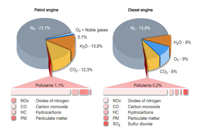
When fuel is burned in the combustion chamber of an engine in addition to harmless products like water, carbon dioxide and nitrogen, some harmful emissions, such as carbon monoxide, nitrogen oxides and hydrocarbons are also produced.
For many years now, a battle has been fought against these harmful emissions on both a political front and by engineers in the automotive industry. For example, at the end of the 1980’s many vehicles with a petrol engine had a catalytic convertor fitted as standard equipment by the vehicle manufacturers which significantly reduced harmful emissions.
The lambda sensor plays a major role in enabling the catalytic converter to fulfill this task because it guarantees the catalytic converter optimal operating conditions.

Exhaust composition
Harmful emissions only represent a very small proportion of the overall emissions of a modern engine. In fact they make up only 1.1 percent of the total for a petrol engine and 0.2 percent of the total for a diesel engine. The majority of the exhaust emitted consists of nitrogen, water and carbon dioxide.
Even so it is important that these comparatively small quantities of harmful emissions are also rendered harmless.
This is necessary because they have significant consequences for our health and well being in even the smallest concentrations.
EURO standards
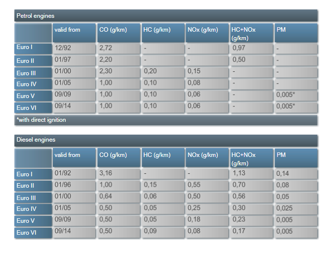
The EURO standards are the legislative specifications that define the upper limits that new vehicles must meet when they are introduced into the market place.
In 1992 the first EURO standard took effect with EURO I. Over time the specifications have become increasingly more strict. Since September 2009, EURO 5 has been in force. EURO 6 is due to take effect in 2014.
Using current practical technologies the limits defined in the EURO standards can’t be met without the use of a catalytic converter. These EURO standards are the primary reason that 135 million of the 162 million (approx.) passenger vehicles currently registered in Europe and fitted with a petrol engine have a factory fitted 3-way catalytic converter as standard equipment.
Position of the lambda sensors
It is a basic requirement that in order for the catalytic converter to work efficiently the air-fuel ratio in the combustion chamber must be controlled very accurately. It is in this area that the lambda sensor plays an essential role.
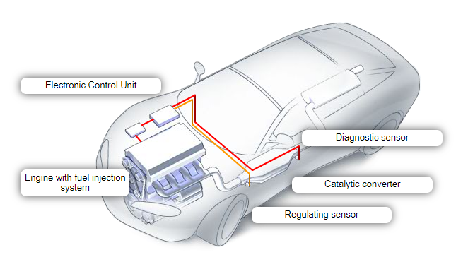
Modern vehicles have at least two lambda sensors. A fuel regulating sensor is positioned up stream of the catalytic converter and - since the legislated introduction of On-Board-Diagnostics (OBD) - a diagnostic sensor is positioned down stream of the catalytic converter.
The lambda control circuit
The fuel regulating sensor measures the residual oxygen in the exhaust gas before it enters the catalytic converter. Depending on the concentration of this residual oxygen the sensor is able to generate a signal which is sent to the engine control unit (“ECU"). The control unit uses this information in order to adjust the air-fuel mixture ratio.
The diagnostic sensor measures the residual oxygen in the exhaust gas after it has been processed by the catalytic converter. On the basis of its signal, the engine control unit can recognise exhaust-relevant malfunctions and report them to the driver, usually by means of a warning lamp on the dashboard.
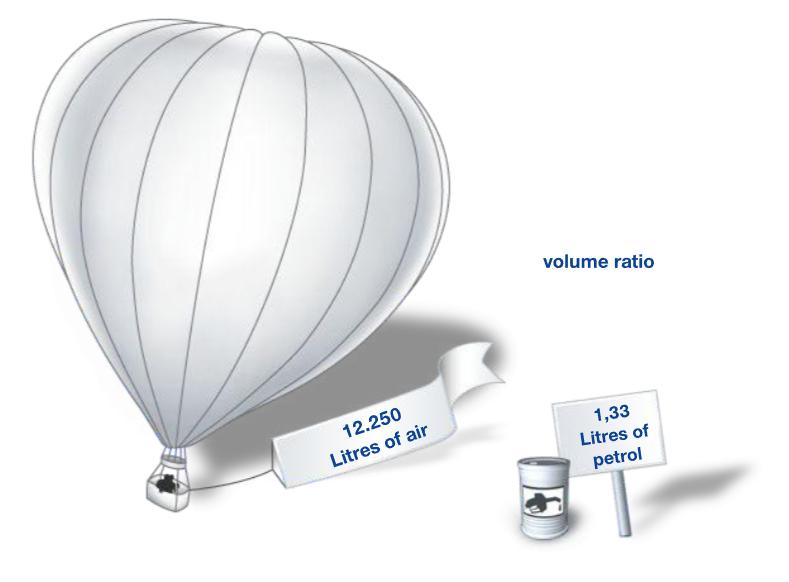
Air-fuel mixture
The theoretical optimum air-fuel ratio for a petrol engine is 14.7:1 which means that 14.7 kg of air would be combined with 1 kg of petrol. This is known as a "stoichiometric mixture“. If an engine is running in this mode it means that the quantity of air supplied to the engine corresponds exactly to the theoretical air requirement to achieve complete combustion of the fuel.
In the motor industry a measure of how close the air-fuel mixture is to the ‘ideal’ is identified by the Greek letter lambda. Only when lambda (λ)=1.0 is the ratio suitable to ensure complete combustion and therefore effective operation of the catalytic converter which converts the exhaust gases almost entirely into more environmentally friendly gases.
Today most petrol engines operate with this mixture. When using other fuel types the air-fuel ratio may be different.
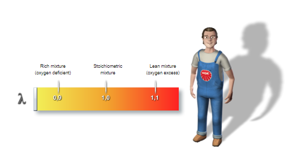
Air ratio
Of course, there are operating modes either side of lambda = 1.0 This air ratio provides information about the respective air-fuel mixture ratio.
If there is more than the ideal quantity of fuel contained in the mixture it is called a rich mixture – in effect the engine runs with a deficiency of air. The air ratio is lambda less than 1.0
On the other hand if there is less than the ideal quantity of fuel - in effect too much air, it is referred to as a lean mixture. The corresponding air ratio is lambda greater than 1.0
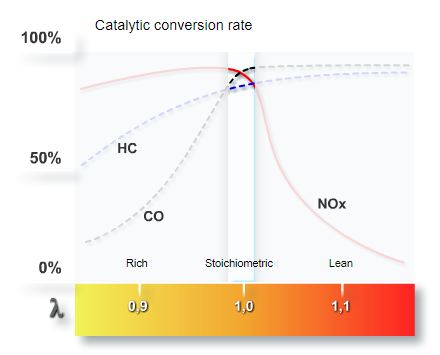
Efficiency of the catalytic converter
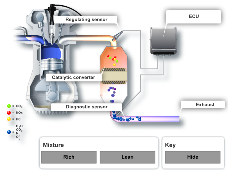
If the fuelling of the engine is kept within a very small window around the stoichiometric mixture (λ=1) , the three way catalytic converter can reduce the harmful emissions of carbon monoxide (CO) and nitrogen oxides (NOx) by more than 95 percent. Unburnt hydrocarbons are also efficiently oxidised to produce carbon dioxide and water.
If the engine is run in a rich state (λ less than 1), the conversion rate is reduced - in particular, the emission of carbon monoxide and hydrocarbons increases significantly.
If the engine is run in a lean state (λ greater than 1) the conversion rate of nitrogen oxides is severely reduced and environmental pollution increases considerably.
Construction
Lambda sensor types
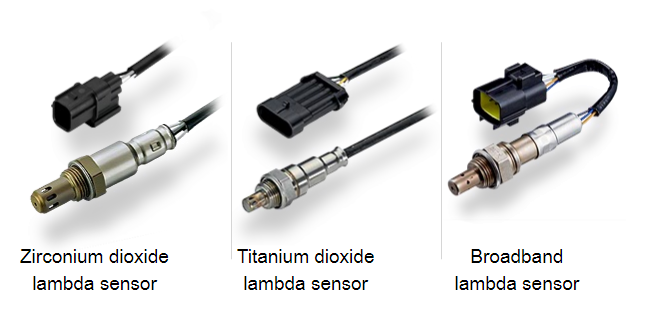
There are basically three different, non-interchangeable types of lambda sensor.
The zirconium dioxide and the titanium dioxide lambda sensors are also called switching, voltage jump, or "binary" lambda sensors, because their output signal varies back and forth between two values depending on whether the fuelling is in a rich or lean state.
The third type is the broadband lambda sensor. They are also known as "linear" lambda sensors because they have an output signal which is proportional to a wide range of air-fuel ratios, can accurately measure those ratios and the transitions between them.
Zirconium dioxide lambda sensor (switching sensor)
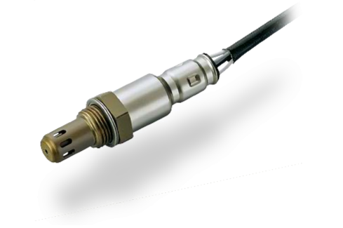
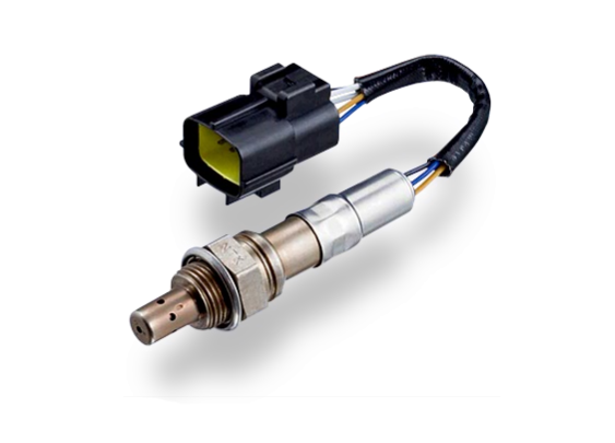
The zirconium dioxide lambda sensor is the most commonly used type. This type of sensor can be used as a regulating or diagnostic sensor, depending on the vehicle.
Zirconium dioxide lambda sensor (switching sensor)
The core of this lambda sensor is a hollow, thimble-shaped zirconium dioxide ceramic element. This material acts as an electrolyte in a similar way to that of the electrolyte found in a car’s battery.
At an operating temperature in excess of 350°Celsius the element becomes permeable for oxygen ions. Early sensor designs used the heat energy of the exhaust gas to raise the temperature of the element but in order to reach and maintain the desired operating temperature rapidly, a built-in heater is connected to the element. In a complex process, essentially dependant on the residual oxygen content in the exhaust, a high or low electrical voltage is generated.
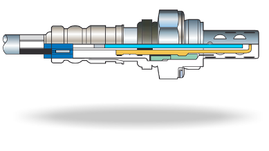
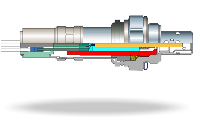
Heater connection
The two white cables (where fitted) are the electrical supply and earth for the integral heating device fitted inside the ceramic element.
Sensor-earth
This cable establishes the earth connection with the vehicle electrical system.
Sensor signal
This cable carries the sensor signal to the engine control unit.
Seal
A special rubber sealing grommet is fitted between the wiring cables and the top of the sensor’s metal housing in order to prevent water ingress into the interior of the sensor. This rubber seal is crimped into the top of the sensor housing.
Hexagon
The hexagon is the contact point used by the appropriate tools to screw the sensor into the exhaust system. When this is carried out attention should be paid to the application of the appropriate tightening torque.
Gasket
The compressible gasket ensures a gas tight seal between the lambda sensor and exhaust system.
Ceramic holder
The ceramic holder ensures that the sensor element is located securely and protects it from vibrations.
Heater
An integrated heater ensures that<br>the sensor element reaches the necessary operating temperature very quickly. This ensures that strict control of the fuelling system takes place within the first few metres of driving and thus make the vehicle operation more environmentally-friendly. This response time before operation commences is called the 'light-off time'.
Modern sensors provide a signal within just a few seconds and thus have a very fast light-off time.
Protection tube
The protective metal tube is designed to allow good gas contact with the element whilst protecting the sensor element from solid particles in the exhaust.
Importantly it also protects the element from contact with any water which may be present in the exhaust system. Water vapour, a product<br>of the combustion process, may condense in the exhaust pipe and if contact with the hot ceramic element occurs damage can result due to thermal shock (rapid change in temperature).
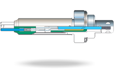
Zirconium dioxide element
The zirconium dioxide ceramic element is in effect a solid electrolyte. The core of this lambda sensor is a hollow, thimble-shaped ceramic element. At an operating temperature in excess of 350° Celsius it becomes permeable for oxygen ions.
Early sensor designs relied on the exhaust gas to raise the temperature of the element but in order to reach and maintain the desired operating temperature rapidly, a built-in heater is connected to the element. In a complex process - depending on the residual oxygen content in the exhaust - a high or low electrical voltage is generated.
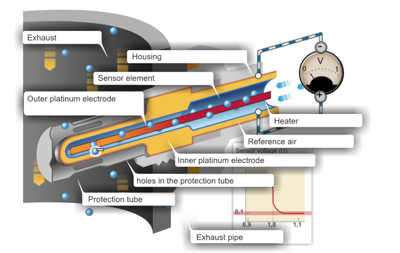
Method of operation of the zirconium dioxide sensor
The zirconium dioxide sensor element has a hollow, thimble-shaped design. The inside surface is in contact with ambient air. The outside surface is situated such that it lies in the stream of the exhaust gas. Both surfaces are covered with a thin, porous platinum layer which act as electrodes.
There will always be a difference in the concentration of oxygen between the exhaust gas and ambient air. When the lambda sensor reaches operating temperature, oxygen ions start to move through the ceramic electrolyte from the side that has a greater concentration of oxygen towards the side that has a lower oxygen concentration attempting to reach a state of equilibrium.
As these ions leave one platinum layer and reach the other layer a potential differential results giving rise to an electrical voltage (U). If the mixture is lean the voltage will be relatively low (approx. 0.1 volts). If the mixture is rich it will be relatively high (approx 0.9 volts). There is a large characteristic voltage jump as the stoichiometric point (λ=1.0) is passed.
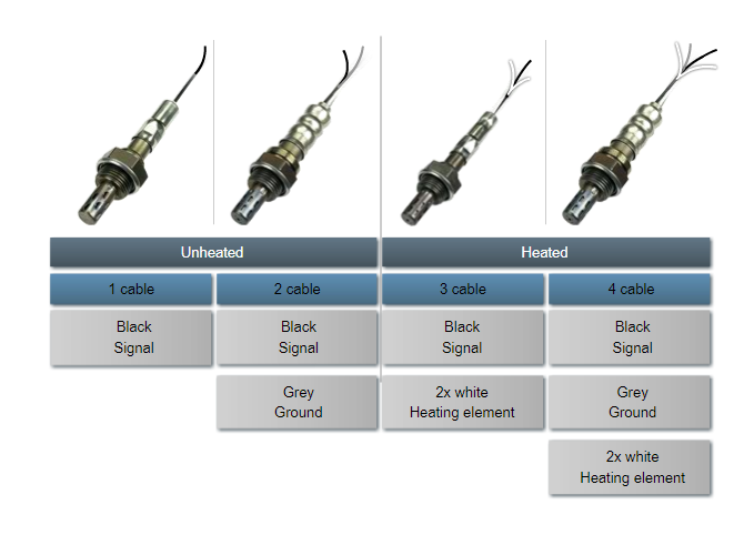
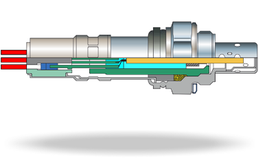
Zirconium dioxide lambda sensor: Cable assignment
Depending on their design, zirconium dioxide lambda sensors can have between one and four cables.
Sensors with a single black cable do not contain a heater and make their earth contact through the threaded section of the metal shell. This single black cable is the sensor output signal line. Sensors without a heater that make their earth contact via the vehicle’s wiring harness have an additional, grey earth cable.
Heated sensors have either three or four cables.
In both cases the black cable carries the sensor signal. The two white cables are the supply and earth for the heater.
Sensors with three cables use the metal shell for their earth connection whereas the four wire types have a grey earth cable to connect to the vehicle’s electrical system.
Titanium dioxide lambda sensor (resistance switching sensor)
This type is known as a metal oxide sensor. Unlike zirconium dioxide lambda sensors, titanium dioxide lambda sensors do not self-generate a voltage. The ceramic element is a semi-conductor, the electrical resistance of which varies relative to the residual oxygen concentration in the exhaust gas. Therefore by application of a voltage to the sensor a varying signal is produced dependant on the oxygen concentration.
All titanium dioxide lambda sensors have an integral heating element. By virtue of their design they do not require access to ambient air for reference. As a result, they are usually more compact than zirconium dioxide types.
The control system for this type is very different to that used for the zirconium dioxide type.
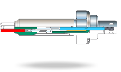
Titanium dioxide element
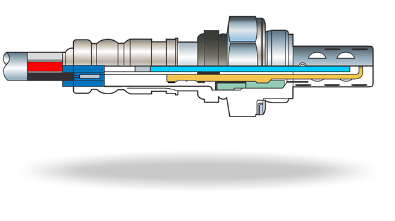
The ceramic sensor element of this lambda sensor is constructed from a metal oxide - titanium dioxide (TiO2) using multi-layer, thick-film technology.
Titanium dioxide element
The ceramic sensor element of this lambda sensor is constructed from a ceramic metal oxide - titanium dioxide (TiO2). The electrodes and heater are printed onto an aluminium oxide substrate and titanium dioxide is deposited on top of the electrodes.

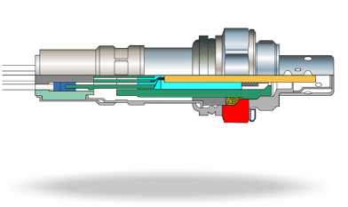
Protection tube
The protective metal tube is designed to allow good gas contact with the element whilst protecting the sensor element from solid particles in the exhaust.
Importantly it also protects the element from contact with any water which may be present in the exhaust system. Water vapour, a product of the combustion process, may condense in the exhaust pipe and if contact with the hot ceramic element occurs damage can result due to thermal shock (rapid change in temperature).
Heater
In order for the lambda sensor to reach and maintain its ideal operating temperature of 700°C as quickly as possible, titanium dioxide lambda sensors are permanently heated.
Gasket
The compressible gasket ensures a gas tight seal between the lambda sensor and exhaust system.
Ceramic holder
The ceramic holder ensures that the sensor element is located securely and protects it from vibrations.
Carrier substrate
The carrier substrate of this lambda sensor is made using multi-layer, thick-film technology from a ceramic material which only serves as the actual carrier for the heater and the element.
Glass seal
The glass seal holds the element in its ceramic holder and secures the attached cable.
Hexagon
The hexagon is the contact point used by the appropriate tools to screw the sensor into the exhaust system. When this is carried out attention should be paid to the application of the appropriate tightening torque.
Sensor ground
This cable establishes the earth connection with the vehicle’s electrical system.
Sensor signal
Through this line the sensor signal is led to the engine control unit.
Seal
A special rubber sealing grommet is fitted between the wiring cables and the top of the sensor’s metal housing in order to prevent water ingress into the interior of the sensor. This rubber seal is crimped into the top of the sensor housing.
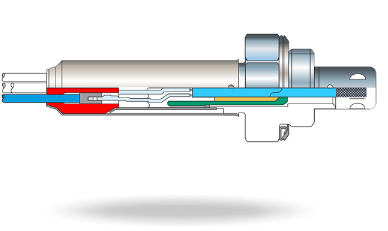
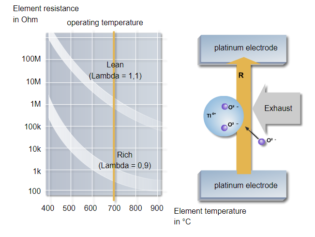
Method of operation of the titanium dioxide sensor
A titanium dioxide element changes its electrical resistance in proportion to the partial oxygen pressure (in effect the oxygen concentration) in the gas mixture.
With a high oxygen concentration (λ greater than 1.0) the titanium dioxide is less conductive; with a low oxygen concentration (λ less than 1.0) it is more conductive.
If a voltage is now applied to the element, the output voltage changes according to the oxygen concentration in the exhaust.
The ideal operating temperature of this lambda sensor is 700°C. Temperatures above 850°C can damage the sensor element.
An additional advantage of this type of sensor: The titanium dioxide sensor does not require any outside air as a reference and is therefore smaller.
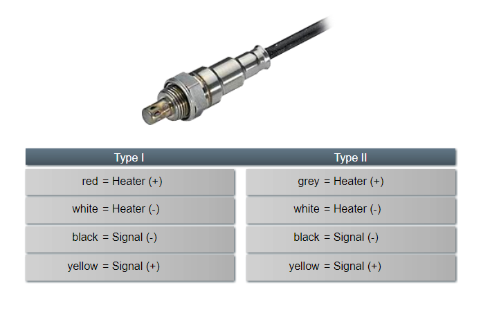
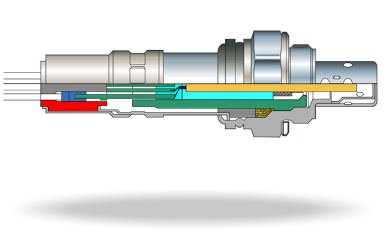
Titanium dioxide sensor: Cable assignment
Titanium dioxide lambda sensors produced by NTK have either three or four cables.
In the four cable types the (+) signal is yellow and the (-) signal is black.
The colour of the cable for the heating element (+) has two variations: For type 1 lambda sensors this cable is red; for type 2 it is grey and for both the heating element (-) is white.
In three wire types the yellow signal (+) cable is omitted.
Broadband lambda sensor
With the ever greater demand to reduce fuel consumption and to lower exhaust emission levels it has become necessary to operate engines away from the stoichiometric fuelling point under certain conditions.
An enriched air/fuel mixture (λ less than 1.0 ) may be required during a cold start and under full load conditions and these areas of operation are closely scrutinised to find new strategies to reduce fuel consumption.
Some more recent engine concepts are designed to operate at an air/fuel ratio much leaner than stoichiometric, at least for part of their operation. These ‘lean burn’ engine strategies must be strictly and accurately regulated.
For this purpose ‘broadband’ sensors were developed. These sensors can accurately measure and produce an output signal which is proportional to a very wide range of air-fuel ratios. Fuelling can be maintained at any required air/fuel ratio. Their operation is both extremely fast and precise.
Broadband sensors are also used in modern diesel engines, which mostly operate with an excess air factor.
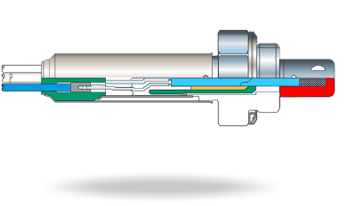
Broadband lambda sensor (planar element with heater)
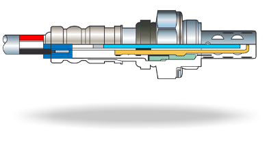
The ceramic element of an NTK broadband lambda sensor can be described as ‘planar’ as it is comprised of multiple layers.
The element is a complex combination of a pump cell, a measurement cell and an integrated heater.
Protection tube
The protective metal tube is designed to allow good gas contact with the element whilst protecting the sensor element from solid particles in the exhaust. Importantly it also protects the element from contact with any water which may be present in the exhaust system. Water vapour, a product of the combustion process, may condense in the exhaust pipe and if contact with the hot ceramic element occurs damage can result due to thermal shock (rapid change in temperature).
Planar element with heater
The planar element of an NTK broadband lambda sensor is comprised of multiple layers.
Along with a pump cell and a measurement cell, it also has<br>an integrated heater.
Element holder
The element holder provides a secure location of the ceramic element and importantly protects it from vibration.
Hexagon housing
A hexagonal nut is formed on the housing providing the contact point for appropriate tools to secure the sensor. Attention should be given to the correct torque tightening values.
Seal
In order to ensure that no moisture penetrates into the sensor, the cables are provided with a rubber seal on the outside. This rubber seal is pressed in over the sensor housing.
Connecting cable
The sensor is connected to the control unit through the connecting cable. The control unit regulates the pump cell and measures<br>the necessary pump flow and evaluates it for the lambda regulation.
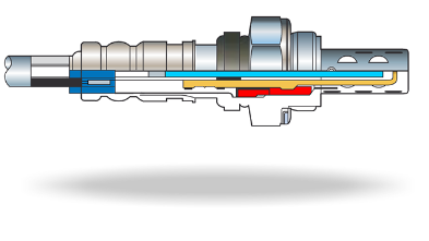
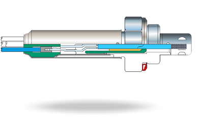
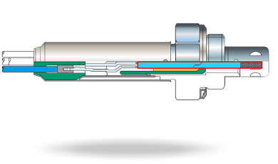
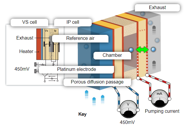
Method of operation of the broadband lambda sensor
Broadband sensors consist of two cells: one measurement cell and one pump cell. With the help of the measurement cell, the oxygen concentration of the exhaust - which is found in the detection chamber - is measured and compared with a target value of 450mV which represents a stoichiometric mixture.
Any deviation from 450mV will cause the pump cell to transport oxygen ions into or, by reversing the current, out of the detection chamber in an attempt to regain the target value.
Measurement of the value and direction of flow of this generated pump current enables precise identification of the air fuel ratio.
At a stoichiometric air fuel ratio there is no net current flow, as the residual oxygen concentration within the detection chamber is designed to produce 450mV at this value.
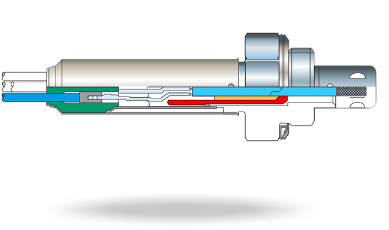
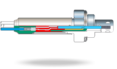
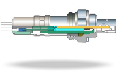
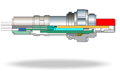
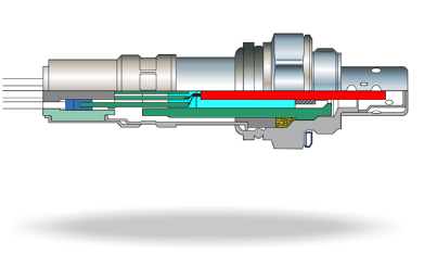
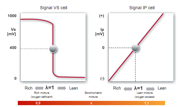
Signal output of a broadband lambda sensor
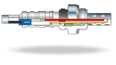
If a stoichiometric mixture is present (lambda = 1.0), no current flows through the pump cell.
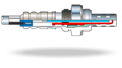
If a rich mixture is present there is very little residual oxygen a negative current is produced at the pump cell and oxygen is pumped into the detection chamber.
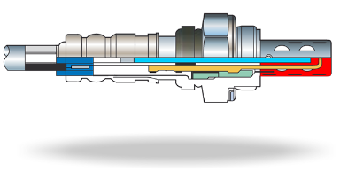
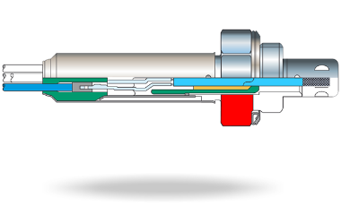
If a lean mixture is present there is more residual oxygen and a positive current is produced at the pump cell and oxygen is pumped out of the detection chamber.
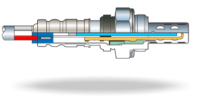
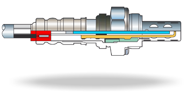
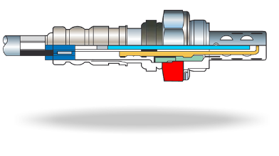
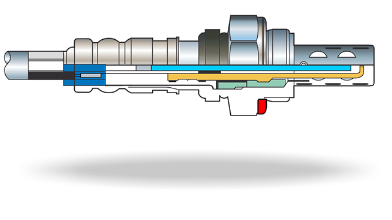
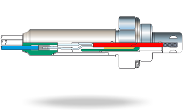
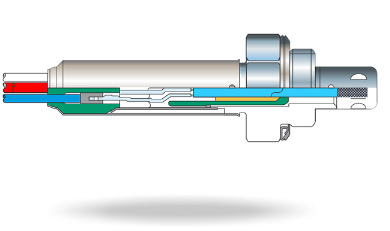
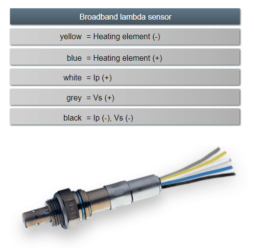
Broadband lambda sensor: Cable assignment
NTK broadband lambda sensors have five cable connections.
The yellow and blue cables provide the heater power control. The pump signal (Ip+) flows through the white cable; the measurement cell signal (Vs+) flows through the grey cable. The black cable provides the earth connection for both pump and measurement cells.
Special sensors
Special sensors
Special sensor types are often necessary for modern applications. For example direct injection petrol engines, motorsport applications and motorcycles place very specific demands on the technologies used for exhaust gas measurement and after-treatment.
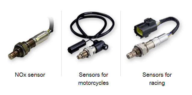
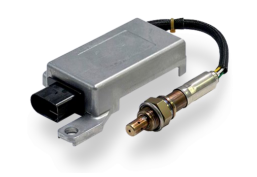
NOx sensors
In order to make petrol engines more economical and environmentally-friendly automobile manufacturers are relying increasingly on direct petrol injection engines which can run at very lean air/fuel mixtures under partial load.
This can result in 12 to 20 percent less fuel consumption - however it also requires the use of a NOx sensor.
In order to operate NOx sensors dedicated electronic control units are required. These form an integral part of the component.
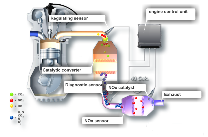
Method of operation of the NOx sensor
In lean, stratified charge mode the operating point of the engine is no longer at lambda = 1.0 and therefore lies outside the optimal conversion window of the catalytic converter. As the converter is no longer operating effectively the emission of nitrogen oxides increases considerably. For this reason an additional NOx storage catalytic converter is used, which temporarily stores the nitrogen oxides.
When the catalyst reaches saturation point and no more NOx can be stored the NOx sensor recognises it. The sensor then instructs the engine control unit to switch to rich operation (λ less than 1.0) for around two seconds.
This strategy allows the nitrogen oxides to be chemically reduced and converted into harmless nitrogen.
This "regeneration phase" repeats about every 60 seconds in lean operation.
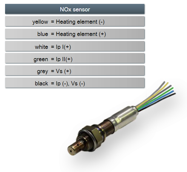
Cable assignment of the NOx sensor
The cable assignment of an NTK NOx sensor is shown here.
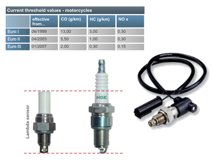
Lambda sensors for motorcycles
Since 1999 there have also been emission limits for motorcycles. Therefore catalytic converters are being fitted as original equipment by many manufacturers even to machines with a small cylinder capacity.
With this market segment in mind NGK SPARK PLUG has developed the special OZAS-S3 lambda sensor. Its zirconium dioxide sensor element is especially resistant to high temperatures allowing the sensor to be installed close to the engine, even into the cylinder head itself. This installation location enables the sensor to reach the necessary operating temperatures very quickly even without a heater.
The advantage: The sensor is particularly compact and lightweight. In addition a simple control system can be employed and the cable is "plugged in" to the sensor in a similar manner to a spark plug.
Lambda sensors for motorsports
Broadband sensors are often used in motorsport because the air-fuel mixture must be very precisely controlled and adjusted, possibly away from lambda=1 to ensure maximum power.
Sensors used in this environment must also be of particularly robust construction because of the demanding conditions found in racing applications. For example, the sensor must maintain complete accuracy whilst being exposed to long periods of extreme exhaust temperatures and very high levels of vibration. Neither of these conditions must damage the sensor or impair the measurement results.
Installation
Installation of a lambda sensor
When fitting a lambda sensor an open ring (pipe) spanner or special lambda sensor socket must be used. Impact wrenches must never be used otherwise damage to the ceramic sensor element can occur.
Great care must be taken to avoid twisting, trapping or otherwise damaging the cable.
Original Equipment (O.E.) quality lambda sensors are ready-to-install and offer considerable advantages: They have the precise cable lengths and dimensions and come complete with the necessary fittings and grommets. In addition there are no compatibility issues to worry about making a trouble free installation possible.
To make installation even easier, lambda sensors from NTK have a special sensor-friendly (silicone free) anti-seize compound applied to the threads.
Diagnosis
Wear and replacement
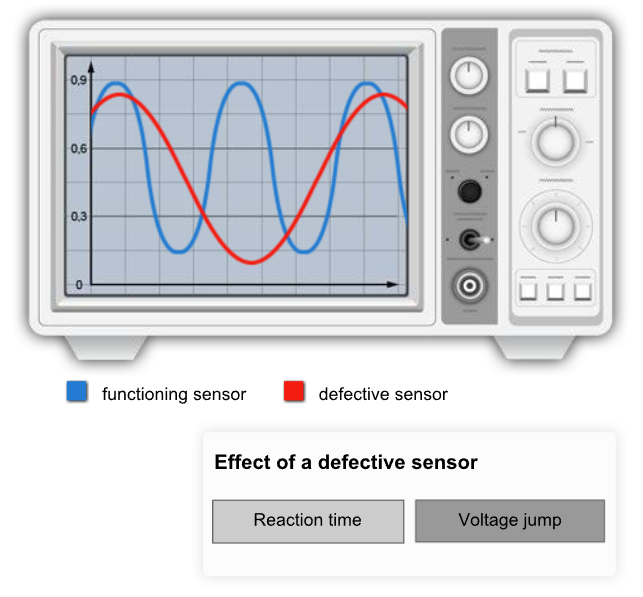
As age and wear increase, the lambda sensor’s response time becomes more sluggish and the jump in voltage becomes less.
That means: The engine control unit does not receive the signal in time or the signal is unusable.
If this is the case, the engine control unit switches to "emergency mode" and runs a rich mixture as a precaution. In this way, an acceptable level performance is guaranteed and components are protected from overheating.
The downside: Fuel consumption increases considerably and more harmful exhaust gases escape to the environment.
Often such a defect goes unnoticed until the next exhaust gas inspection. The engine, in effect burns more fuel, wasting money with every kilometre covered and pollutes the environment more than necessary.
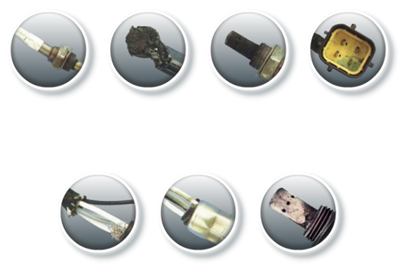
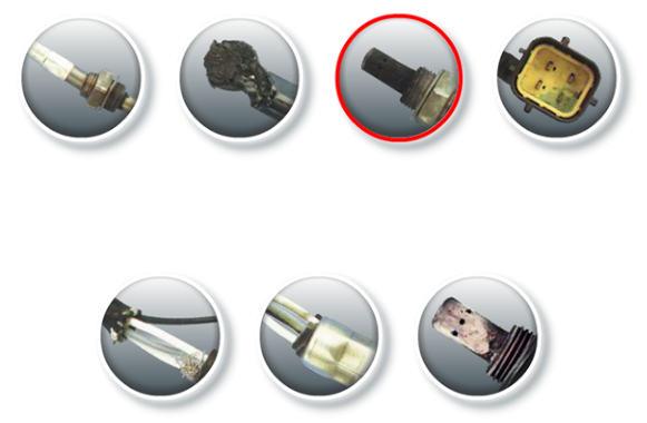
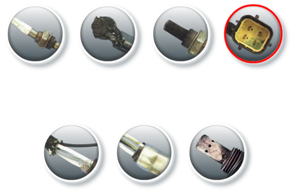
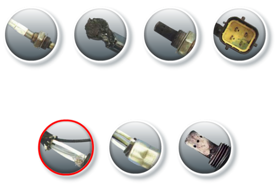
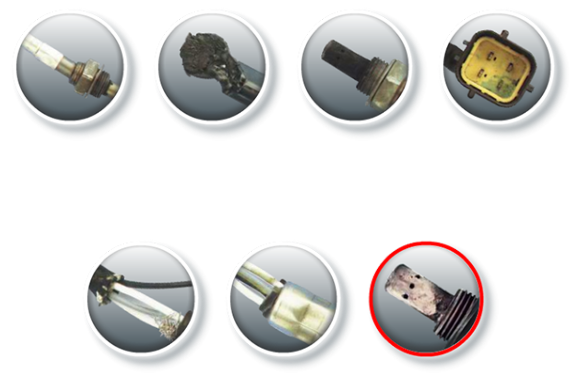
Visual inspection
The lambda sensor is subject to high thermal loads, vibrations and aggressive chemical compounds. Installation errors can also lead to malfunction. Here you can see the most common defects.
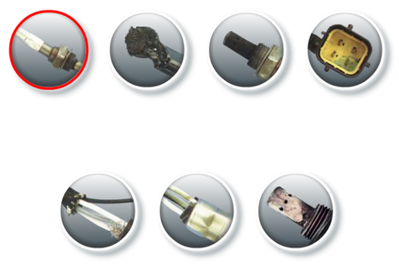
Bent sensor
The sensor was probably installed incorrectly or has suffered impact damage. The signal output can be disrupted as a result. The sensor should be replaced.
Cable or plug melted
Damage such as this usually result from contact with the exhaust system. The sensor must be replaced.
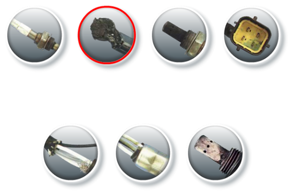
Carbon deposits
The protective tube shows signs of heavy carbon deposits. This can arise from a mixture which is too rich, high oil consumption due to a worn engine or valves and leakage in the exhaust system. Since the carbon deposits block the openings in the protective tube, the sensor can no longer work properly.
Corroded contacts
In this case water has penetrated the connector housing causing corrosion of the contacts. On replacement of the sensor, the sealing of the plug as well as all connections between the sensor and engine control unit must be closely inspected.
Frayed/broken cable
The sensor cables were probably subjected to a heavy pulling load. On replacement, ensure that the cable not routed too tightly and under no tensile stress.
Cable seal displaced
The sensor cables were probably routed too tightly. Water can penetrate. The sensor should be replaced.
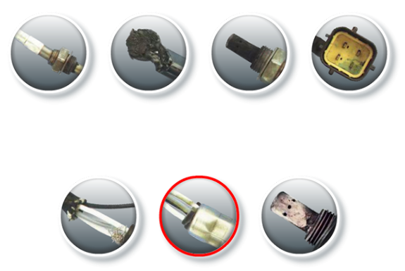
White/grey deposits
Heavy white or grey deposits indicate that fuel additives are used or oil is being burnt. After rectifying the cause, the sensor must be replaced.
Testing zirconia switching lambda sensors
Testing with an oscilloscope is the most effective method. It shows minimum and maximum voltage, the response time and the frequency. When performing this test, the manufacturer's specifications must be observed.
Test procedure:
- Bring the engine to operating temperature at 2,000 rev/min.
- Connect the oscilloscope to a signal line without disconnecting the sensor from the engine control unit.
- Set the measurement range to 1 - 5 volts, time to 5 - 10 seconds (observe manufacturer's specifications).
- If applicable, activate automatic signal recognition.
A correctly functioning sensor swings between 0.1 and 0.9 volts with a frequency of 0.5 - 4 Hz.
Diagnosis tips
A visual inspection often provides the initial clues for a possible malfunction. Inspection points for the workshop are:
Resistance value of the heating element:
Cables:
Are they broken or is the plug broken?
Is the cable seal intact?
Has moisture penetrated into the plug?
Are the plug contacts in good condition?
Is the cable routing too tight?
Sensor body:
Does the sensor show any visible damage?
Each vehicle type will have a specifically designed sensor type and therefore it is essential that they are only replaced with matching specification sensors.
It is very important to use the current NTK catalogues to identify the correct replacement sensor for each application.