Ignition cables
Principles
Function of ignition leads
The ignition leads are responsible for conducting the necessary voltage (U) to the spark plug with as little loss as possible.
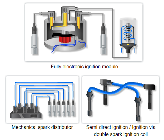
This is achieved – depending on the type of vehicle – using:
- a mechanical spark distributor and distributor cap.
- a fully electronic ignition module.
- a fully electronic semi-direct ignition or double spark ignition coil.
Since the ignition voltage (U) of up to 36,000 volts is in the high-voltage range, the ignition leads have to be protected accordingly against overvoltage. The ignition voltage must never permeate the insulation and flow to ground, since this could cause misfiring.
Development of the ignition system
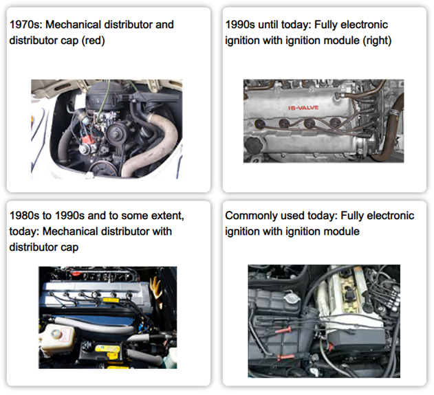
Until the early 90’s it was normal for the ignition system to have a distributor fitted with contact points, these points which are controlled by the engine control unit in the distributor trigger the ignition coil at the correct time. The resulting spark from the coil flows from the coil via the king lead to the distributor cap and is directed to the relevant cylinder via a rotor arm in the distributor.
At the end of the 80’s the contact points were replaced by a solid state switching system in the distributor, usually a ‘hall effect proximity sensor’. This enabled the ignition coil to be switched via an ignition amplifier. This system provides more accurate control over the spark and was more reliable than the earlier mechanical system due to the removal of the contact points and condenser.
The current systems, known as the ‘direct ignition system’ dispenses with the need for a distributor. The spark is controlled by the engine control unit (ECU) which provides very precise spark control usually to a separate coil for each cylinder or a double ended coil providing the spark to two cylinders.
Electro-magnetic compatibility (EMC)
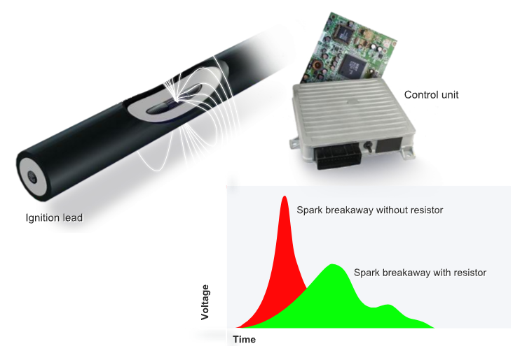
Wherever electric current flows, electromagnetic fields are formed, as for example in mobile phones and radio waves.
Such electromagnetic fields also occur during ignition. They increase considerably in intensity at the time of each "spark breakaway" on the center electrodes of the spark plug – resulting in strong voltage peaks along the lead.
However, since strong electromagnetic fields can cause disturbances in electronic devices – such as the radio, engine or transmission control units or the ABS – they have to be kept within a non-damaging range.
For this purpose, ignition leads are equipped with electrical resistors. They limit the voltage peaks during the spark breakaway and during discharge of the ignition coil.
Construction
Types of ignition leads
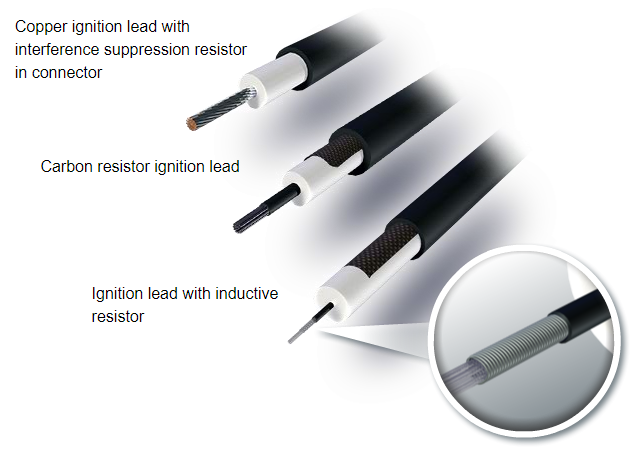
There are three different types of ignition leads. They differ based on the materials used for the conductor and the type of resistor required for interference suppression.
- Copper ignition leads with interference suppression resistor in the connectors
- Carbon resistor ignition leads
- Ignition leads with inductive resistor
The casing of all NGK lead types is manufactured from high grade silicone rubber. Compared to PVC this material is far more resistant to becoming brittle and cracked even at temperatures up to 220°C and in contact with oil or petrol.
It therefore complies with the highest class for temperature resistance in accordance with ISO 3808 (Class F, up to 220°C).
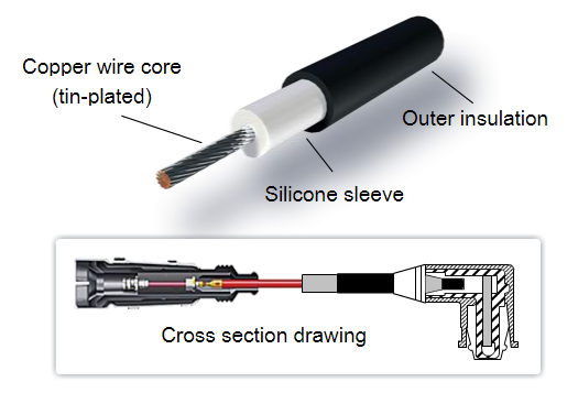
Ignition leads with a copper core
Copper is an excellent conductor, but it can be subject to corrosion. Therefore, the copper core of such ignition leads is tin-plated. The tin layer protects the copper from oxidation.
The copper core is enclosed in a silicone shell for increased stability and electrical insulation.
The outer insulation, made of silicone rubber, can withstand temperatures up to 220°C and is resistant to petrol and oil.
Ignition leads with a copper core are not equipped with their own interference suppression resistor. Instead, the resistor is integrated in the spark plug connector and coil connector in the form of a conductive glass seal. Depending on the lead it is between 1 and 6.5 kΩ.
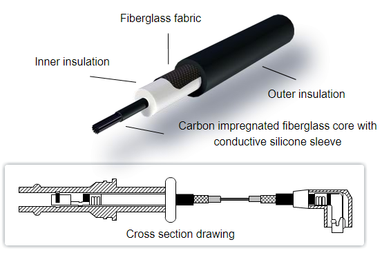
Carbon resistor ignition leads
Inside of a carbon resistor ignition lead there is braided carbon impregnated fiberglass.
This fiberglass core is surrounded by two silicone layers and fiberglass fabric. The inner insulation made of silicone provides for stability and electrical insulation. The fiberglass fabric increases the tensile strength. The outer insulation, made of silicone rubber, can withstand temperatures up to 220°C and is resistant to petrol and oil.
For carbon resistor ignition leads, the interference suppression resistance is usually in the region of 10 kΩ - 23 kΩ per metre.
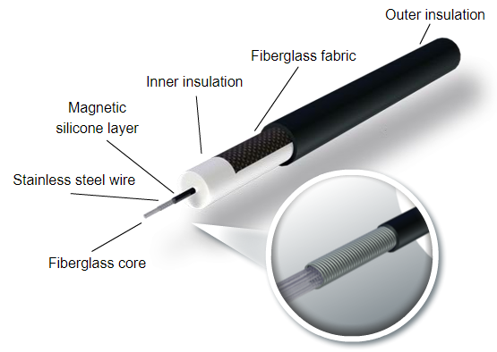
Ignition leads with inductive resistor
There is also a fiberglass core in the interior of this type of ignition lead. Over the fiberglass there is a conductive and magnetic silicone layer, around which a stainless steel wire is wound. As in a coil, inductive voltage occurs here (electromagnetism).
A magnetic field rises and falls in such ignition leads. The coil wire picks up and delivers energy. As a result the inductive voltage is internally cancelled through the lead. That is why it is called "reactive energy" and the resistance in an inductive resistor is referred to as "reactance".
Ignition leads with inductive resistors are surrounded by two silicone layers and fiberglass fabric. The inner insulation made of silicone provides for stability and protects against high ignition voltages. The fiberglass fabric increases the tensile strength. The outer insulation, made of silicone rubber, can withstand temperatures up to 220°C and is resistant to petrol and oil.
One meter of this type of lead has an interference suppression resistance of 1,8 kΩ to 2,2 kΩ.
Installation
Installation instructions
- All electrical connections of the ignition system may be connected or disconnected only with the ignition switched off.
- Ideally, a special ignition lead tool should be used. If such a tool is not available, the installation should always be carried out with tension or pressure on the spark plug connector. Pulling on the lead itself can cause it to become damaged or broken.
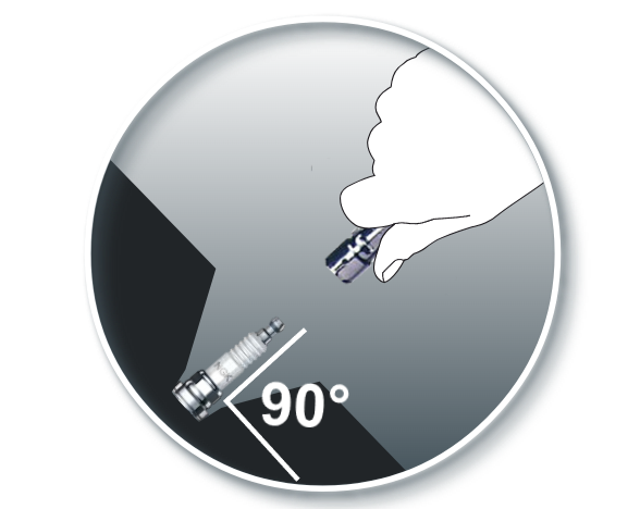
- It is always advisable to twist the connector (¼ turn) before pulling the same.
- Always pull the connector straight away from the spark plug, otherwise the ceramic part of the spark plug could be damaged.
- When routing the leads, make sure that they are not bent or crushed. You should also avoid contact with hot engine parts.
- Each lead has a different length and is measured exactly. Therefore, it is essential to use the right lead for each plug.
Diagnosis
Wear
Due to their installation location, ignition leads are subjected to high stress. As they age, brass/stainless steel connector contacts tend to oxidize. The electrical resistance of the lead increases – together with the risk of the ignition coils failing.
The casing also ages. Because plasticizers escape from the plastics, they become brittle over time. High temperatures and contact with oil or fuel vapors can accelerate this process or even cause the plastics to dissolve.
Damaged insulation causes the ignition voltage to flow to ground. This would result in misfiring, rough engine running and unburned fuel in the catalytic converter, which would then be damaged during post-combustion.
For this reason, the ignition leads should be inspected regularly and replaced at the first signs of aging.


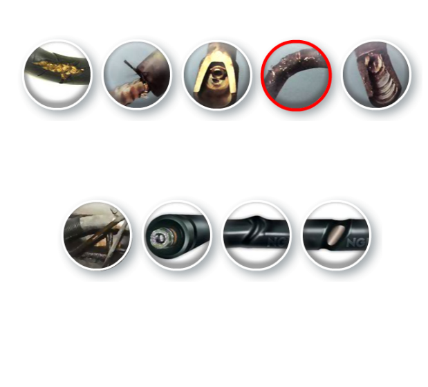
Appearance
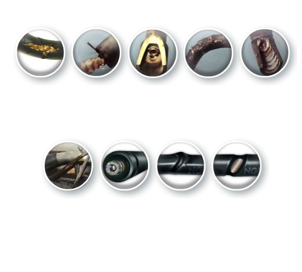
Due to overaging
Due to overaging, the outer sleeve of this lead is cracked and brittle. Ignition voltage can flow to ground, which is undesirable.
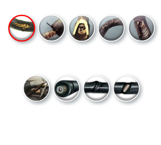
Connector is torn from the lead
Here, the connector is torn from the lead – as a result of incorrect removal.
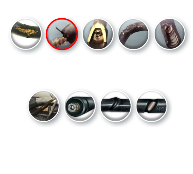
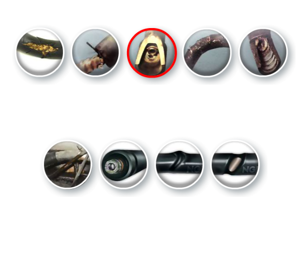
Spark arced over
As can be seen on this (cut open) connector, the spark arced over next to the actual spark plug contact. This is the result of incorrect installation.
Due to overaging
Due to overaging, the outer sleeve of this lead is cracked and brittle. Ignition voltage can flow to ground, which is undesirable.
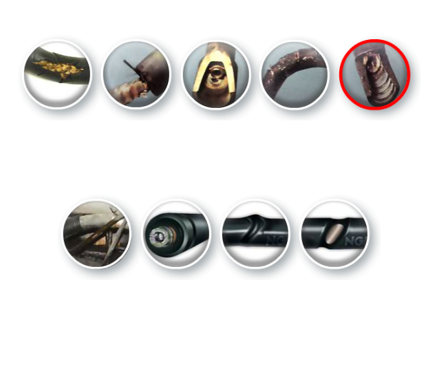
Connector is damaged
The spark plug contact in the connector is damaged. Such damage or disconnecting can result from frequent misfiring or if moisture penetrates the connector. Incorrect installation can also result in such defects.
Damage the outer sleeve
Motor oil can damage the outer sleeve of the ignition lead.
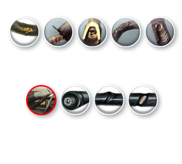
Oxidized plug contacts
Oxidized plug contacts: Moisture has penetrated as a result of a loose connection. The oxidized contacts cause an increase in the resistance of the ignition lead and prevent optimal ignition.
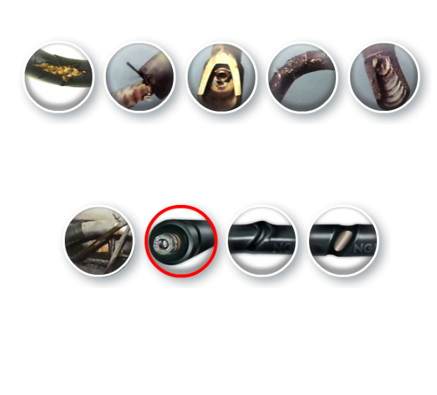
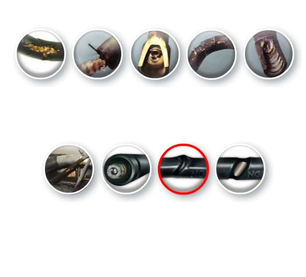
The plastic sleeve is deformed
The plastic sleeve is deformed: Probably due to incorrect routing in the engine compartment. It would be advisable to replace the ignition lead, even if it still functions – for the time being.
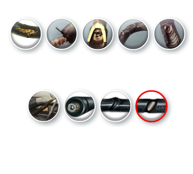
Plastic sleeve is defective
Plastic sleeve is defective: This is often the result of incorrect installation, for example when the ignition lead was pressed on using a screwdriver. In any case, the lead must be replaced.
Testing of ignition leads
First, the ignition lead should be subjected to close visual inspection. If it is porous, has hairline cracks, oxidized contacts or other damage, it has to be replaced.
If the ignition lead appears to be OK, its function can be measured using a multimeter.
- Set multimeter to 20 kΩ.
- Attach one contact to each end of the lead.
- Read the resistance.
Permissible resistance values are:
- Ignition lead with a copper core: 1 to 6.5 kΩ
- Inductive resistor & carbon resistor: The value is calculated based on the resistance per meter multiplied by the length of the lead, plus tolerance. An online calculator is available here.