ESPS (Engine Speed & Position Sensor)
Principles
What do they measure?
Function/ Task
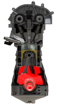
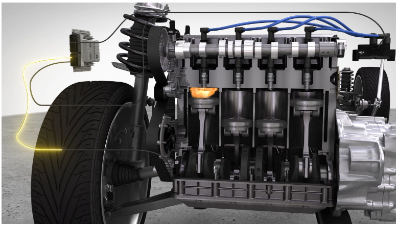
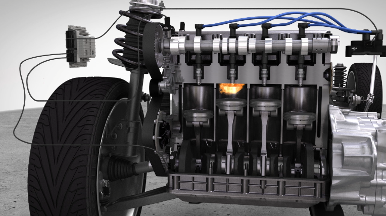
These sensors provide information about the exact position and the speed of several engine parts.
Speed:
- Crankshaft
Position:
- Piston
- Camshaft
- Valves
Tasks
- To ensure fuel injection and ignition in all engine operating conditions, the engine control unit (ECU) must receive information about engine speed and position.
- The crankshaft signal is used to determine the engine speed. In addition, it provides the information when the first cylinder is at top dead center.
- The camshaft sensor gives the information in which stroke each cylinder is.
- From both signals, the engine control unit (ECU) can now regulate when fuel is injected and when the fuel/air mixture is ignited by the spark plugs.
- If the camshaft sensor fails, the engine control unit (ECU) can operate an emergency program from the signal of the crankshaft sensor.
- If the crankshaft sensor fails, the information from the camshaft sensor is not sufficient to keep the engine running.
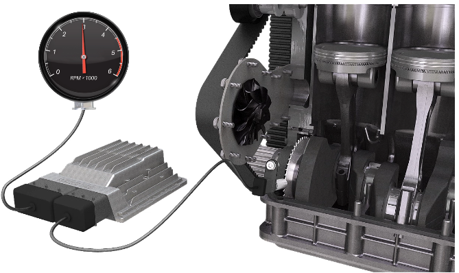
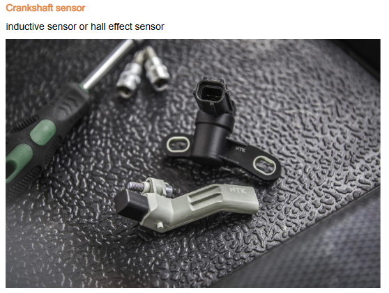
Crankshaft (speed) sensor
- The crankshaft sensor measures the rotational speed and position of the crankshaft.
- This is the most important information the engine control unit (ECU) needs to be able to work.
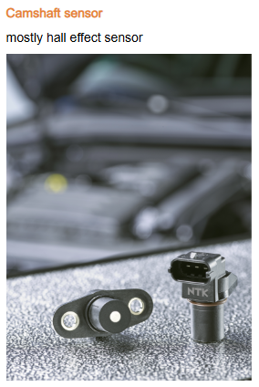
Camshaft (position) sensor
The camshaft sensor measures the position of the camshaft. This signal - in conjunction with the crankshaft position - is used to determine in which stroke each cylinder is. The ECU needs the signal to determine when to inject fuel and to operate the spark plug.
Crankshaft sensors
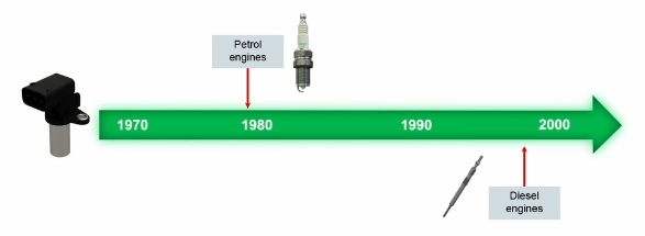
Used for petrol and diesel engines with electronic injection systems. Petrol: starting in 80s (“Motronic” 1979); from 1990 almost all cars have crank sensors. Diesel: starting with “common rail” technology, 1997 (Alfa 156 JTD).
Camshaft sensors
- Used for petrol and diesel engines with electronic injection systems.
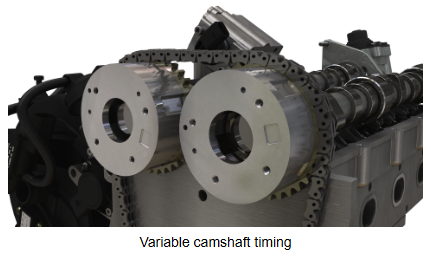
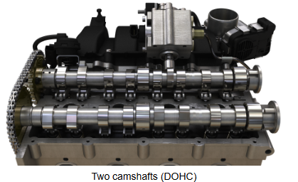
- Many newer engines have two camshafts, and often (not always) two camshaft sensors.
- With variable camshaft timing, the sensor(s) also are used to monitor this function.

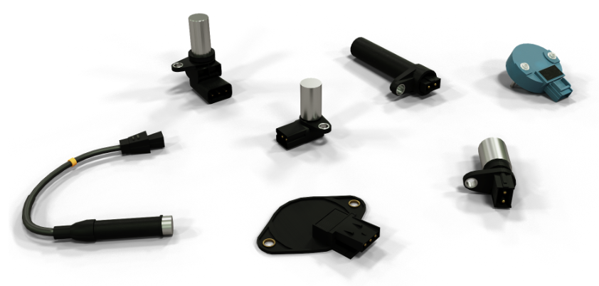
Appearence of crankshaft sensors
History/ Evolution
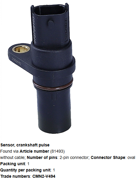
Different designs of crankshaft sensors
Main differences:
- 2 or 3 Pins
- With or without wire
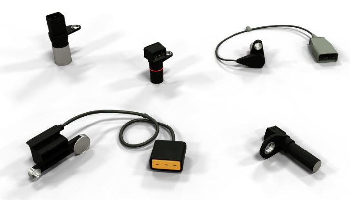
Appearence of crankshaft sensors
History/ Evolution
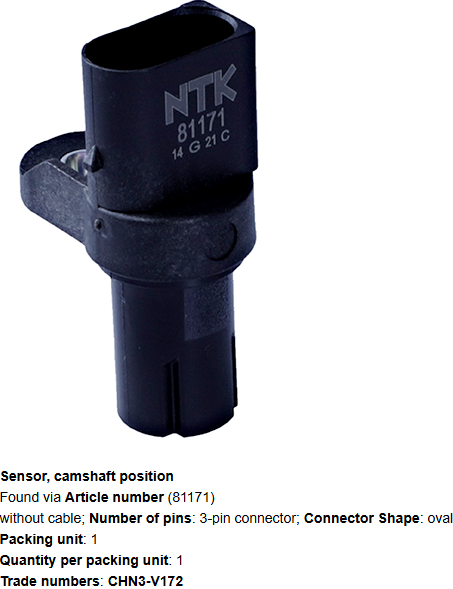
Different designs of crankshaft sensors
Main differences:
- Mostly 3 Pins
- With or without wire
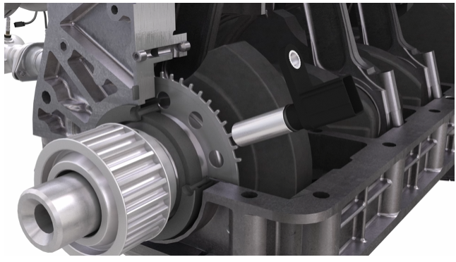
Installation position - Crankshaft (speed) sensor
- The crankshaft sensor is installed near the crankshaft, in or near the lower engine block.
- It picks up the signal of a toothed wheel or disk which rotates with the crankshaft.
- The sensor can be at either side (drive belt or flywheel side) of the crankshaft, or in the middle.
- In some cases in contact with oil.
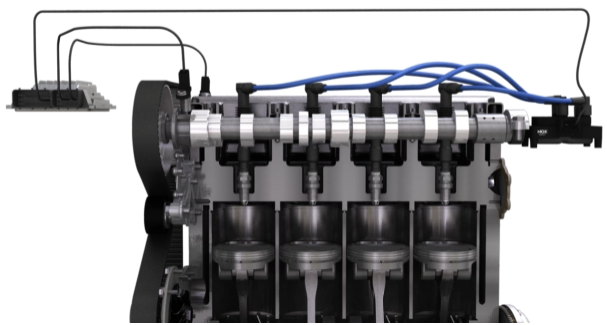
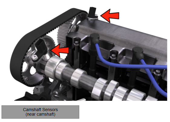
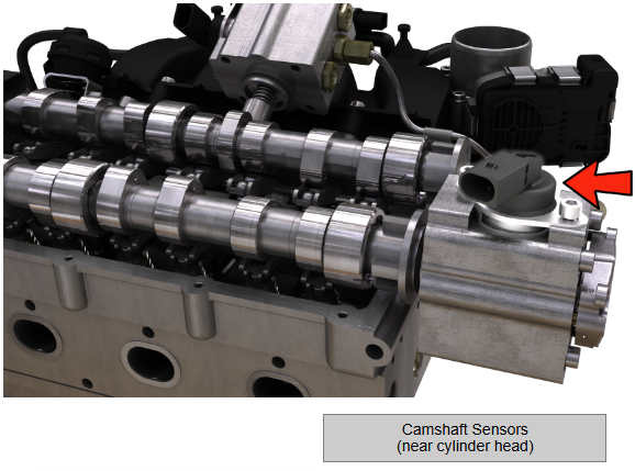
Installation position - Camshaft (position) sensor
Camshaft position:
The position of the camshaft is (together with crankshaft position) an indicator for the position of the piston and allows for the ECU to determine in which stroke each piston is.
The camshaft sensor(s) is installed near the camshaft(s), in or near the cylinder head.
Construction
Operating principle
- The sensors operate either according to the inductive principle or the hall effect principle.
- They can not be interchanged.
Induction principle
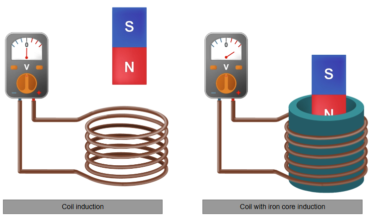
Electromagnetic induction is the occurrence of an electrical voltage along a conductor loop (e.g. a coil) due to a change in magnetic flux.
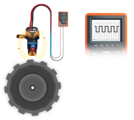
The induction principle can be easily illustrated with a simple experiment.
A coil is connected to a sensitive voltmeter.Then a magnet is moved through a coil. The movement generates an electric voltage because the magnetic flux changes. During the movement of the magnet, a voltage can be measured. The faster the movement, the higher the measured voltage.
However, the voltage generated is very low. To enhance this effect, the coil is looped around an iron core. The iron core amplifies the magnetic field because the elementary magnets (the atoms in its metal grid) align themselves according to the magnetic field.
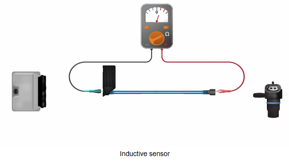
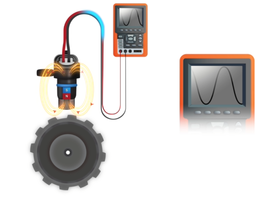
Inductive sensor
The sensor consists of a coil with an iron core in the middle. Underneath is a magnet that generates a magnetic field.
Due to its installation position, the sensor is aligned in such a way that the magnetic field of the magnet can be affected by the toothed wheel of the crankshaft.
When the wheel starts to turn, the magnetic field moves up and down, generating an electrical voltage in the coil.
The faster the wheel turns, the higher the voltage generated.
Hall effect principle
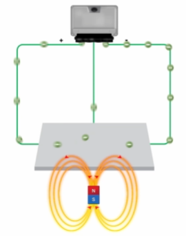
The hall effect occurs when a current carrying conductor is affected by a magnetic field. The magnetic field affects the electrons moving through the electrical conductor. It moves the electrons perpendicular to both the current flow direction and the magnetic field direction. That results in a voltage that can be measured perpendicular to the current flow.
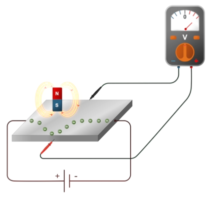
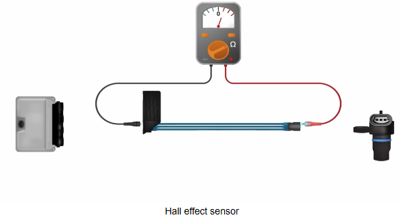
Hall effect sensor
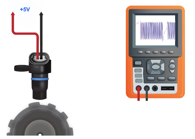
The sensor consists of an electrical conductor, which is supplied with either 5V or 12V voltage by the ECU. If a magnetic field affects the current carrying conductor, the Lorentz force acts on the electrons. This results in a surplus of electrons on one side and a shortage of electrons on the other. The charge difference can be measured in the form of a voltage and is transmitted to the ECU via the signal line. The simplified schematic shows the current flow with and without the influence of the magnetic field.
Hall effect sensor
If the magnetic field is now moved alternately to the sensor and away again by a toothed wheel, a square output signal of 0 to 5V or 12V is generated.
The faster the wheel turns, the shorter the time period between high and low level.
Crankshaft speed and Position detection
- By a “trick” the ECU can detect crankshaft speed and crankshaft position at the same time.
- The toothed wheel has one bigger gap, at a dedicated position.
- The signal generated by the sensor reflects this big gap, and so the ECU can calculate the position.
- This characteristic in the signal is called the reference mark. With inductive sensors, a larger voltage peak occurs at this point compared to the rest of the signal. With hall effect sensors, a slightly longer high level period occurs at this point.
Comparison hall effect sensor and inductive sensor
Hall effect sensor | Inductive Sensor |
|---|---|
Integrated electronics | No Integrated electronics |
External power supply 5V | Generates a signal, no external power supply |
Square output signal (0V/5V) | Wave-form output signal |
Voltage does not rise with wheel speed | Voltage rises with wheel speed, and depends on distance to wheel |
3 Pins | 2 or 3 Pins (3rd for shield) |
Speed detection at near standstill (low speed detection) | Speed detection only possible above a certain speed. |
The design of the sensor is smaller and lighter | The design of the sensor is larger |
The sensitivity to electromagnetic interference is lower | The sensitivity to electromagnetic interference is high |
Changes in the air gap between the sensor and the toothed wheel have no direct effect on the signal | Changes in the air gap between the sensor and the toothed wheel have direct effect on the signal |
Higher resistance to vibrations and temperature fluctuations | Lower resistance to vibrations and temperature fluctuations |
Installation
Installation
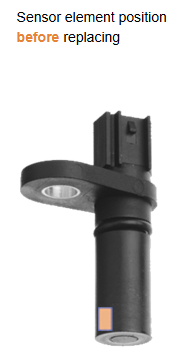
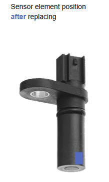
- After installation of new cam and crankshaft sensors many cars require a „learning“ procedure. A scan tool is required for this.
- The Engine control unit (ECU) will „learn“ the exact position of the sensor.
Background: the hall sensing elements in the sensor housing are not necessarily at the same position as the old sensor. This causes the signal to come a bit later or earlier.
Diagnosis
Consequences of sensor failures
Camshaft
- Without that signal, the ECU can (in most cars) keep the engine running.
- The engine starts delayed. The engine runs in the emergency program. The MIL lights up.
- Variable camshaft timing (if the engine has this function) will not work.
Crankshaft
- Without that signal (main input signal for the ECU), the ECU can not keep the engine running.
- The engine does not run and start.
Symptoms of a defective crankshaft sensor
- In most cases the engine will not run and a DTC (diagnostic trouble code) will be stored.
- Sometimes the error occurs sporadically. The following symptoms indicate a defective crankshaft sensor:
- Bad starting
- Jerking engine
- Engine stalls / dies off
- Bad performance
- Misfiring
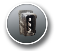
Corroded contacts
In this case water has penetrated the connector housing causing corrosion of the contacts. When the sensor is replaced, the connector seals, the connector contacts, and the wires between the connector and the engine control unit should be thoroughly checked.
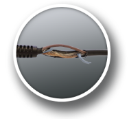
Broken/frayed cables
The cables have been damaged by external force. This can be caused by a strong pulling movement (cable laid too tightly, pulling on the wire while mounting) or by rotating parts (cable rubbing against rotating parts, e.g. crankshaft wheel). Therefore, pay attention to the correct cable routing during installation.
Gap too big
The gap between the gear and the sensor is too large, causing the signal to become weaker.<br>This problem can be caused by an incorrectly installed sensor or a sensor that is not suitable for the engine.
Damaged toothed wheel
The toothed wheel is mechanically damaged.
A mechanically damaged gear on which one or more teeth are damaged or broken can cause a malfunction of the signal. Therefore, the toothed wheel should also be subjected to a visual inspection.

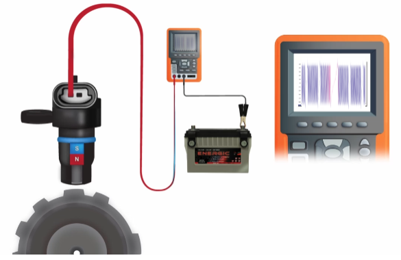
Testing of cam and crankshaft sensors
The best way to determine if the cam or crankshaft sensor is working properly is to check if the signal is correct. An oscilloscope is the right tool for this.
First, you need to determine if you are expecting a hall or inductive signal.
A good indicator is whether the sensor has 2 or 3 pins. If it has 2 pins, it is most likely an inductive sensor and if it has 3 pins, it is most likely a hall effect sensor. But there are some exceptions, sometimes an inductive sensor can have a 3rd pin for shield.
A good way to identify NTK sensors is by the trade number. If it starts with "CM", it is an inductive sensor and if it starts with "CH", it is a hall effect sensor.
Testing inductive sensors
- Connect the measuring outputs of the oscilloscope with pins 1 and 2 of the sensor.
- Select the oscilloscope preset so that you can clearly see signal of the sensor. To evaluate the signal, it is best to visualize two crankshaft revolutions. The settings must be adjusted with increasing engine speed to keep the signal visible. Here is some information that may help in setting the X and Y axis:
Y axis: | X axis: |
|---|---|
| Signal voltage at least 0,5V while starting | Somewhere between 100 and 200 msec to make two complete crankshaft revolutions visible |
Signal voltage at least 2V at idle speed | |
Signal voltage increases with engine speed |
- The voltage peaks should not differ greatly from each other except for the reference mark. A deviation of 20-30 percent is a normal deviation for many vehicle manufacturers. Deviations above this indicate damage to the pulse wheel.
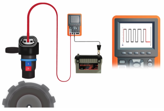
Testing hall effect sensors
- Connect the measuring outputs of the oscilloscope with the pin of the signal line of the sensor and the battery ground (terminal 31).
- Select the oscilloscope preset so that you can clearly see the signal of the sensor. To evaluate the signal, it is best to visualize two crankshaft revolutions. The settings must be adjusted with increasing engine speed to keep the signal visible. Here is some information that may help in setting the X and Y axis:
Y-axis: | X-Axis: |
|---|---|
| Signal voltage either from 0-5V or 0-12V | Somewhere between 150 and 200 msec to make two complete crankshaft revolutions visible at idle speed. |
Time period between high level and low level increases with engine speed |
Testing hall effect sensors
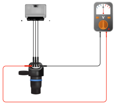
- If no signal is detectable with the oscilloscope or the signal voltage is too low, there is most likely a problem with the power supply of the sensor. To check the power supply of the sensor you can measure the voltage between the plus and minus wire of the sensor. Depending on whether the circuit is 5 V or 12 V, a corresponding measured value is expected.
- If you can't measure a signal on the pin of the signal line of the sensor and the power supply is found to be alright, the sensor is defective.
Further tests of the sensor circuit
To check this result you can check the resistance of the cables between the engine control unit and the sensor. The cable must be measured in a current free state to avoid damage to the circuit. To do this, disconnect the connector on the engine control unit and on the sensor. The resistance can vary depending on the cable length and diameter, but a resistance value of approx. 1 Ohm is a normal value for a functioning cable.