Wide Band Lambda Seonsors
Continuous and constant effort from worldwide authorities to achieve a reduction in polluting emissions in the transport sector, moreover in internal combustion engine cars, caused the emissions control systems to evolve, by introducing new catalytic converters, upstream and downstream lambda sensors working on such converters, exhaust gas recirculation systems (EGR), temperature sensors, NOx sensors and reduction catalysts for NOx (SCR). The mutual interaction between such systems took the thermal engine to work outside the stoichiometric ratio (λ=1) and caused the need to control how engines work outside such an operating range. So wide band lambda sensors were born.
Working principle
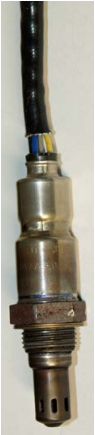
A wide band lambda sensor (also known as ‘wide range’ or ‘broad band’) measures the residual oxygen concentration in exhaust gas and, compared to traditional titania dioxide and zirconia sensors which can only detect lambda 1, it is suitable for measuring wider air/fuel mix ranges. Internal operation differs from a traditional sensor. A wide band sensor is internally equipped with two fundamental cells, one for measuring and one for pumping: in the first, oxygen concentration is measured and then converted into a volt signal, which is compared to a reference voltage of 450 mV; such voltage represents a nominal value associated to the stoichiometric ratio of λ=1. When this value deviates from the reference value, the pumping cell pumps oxygen ions in/out of the measuring cell, correcting the oxygen concentration in such cell, so the 450 mV reference voltage can be maintained. The value and polarity of current required by the pumping cell to maintain the constant concentration represents the value equivalent to oxygen concentration in the mixture.
Vehicle examined:
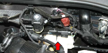
VW PASSAT VII 1.6 TDI 88 kW
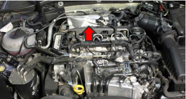
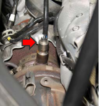
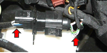
Location: For the vehicle example chosen, the lambda sensor is mounted behind the engine, after the turbocharger and before the catalytic converter (position generally referred to as ‘precat’ or ‘front’). The connector is located in the engine bay, left side, close to the brake fluid reservoir. The sensor itself has 5 wires and the vehicle harness has 6.
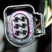
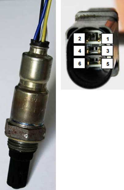
Note: The sensor has five wires although the sensor connector has 6 terminals inside. Two pins are internally connected by an integrated resistor inside the connector itself. In this instance, it is pins shown below as 1 & 2 (note; wire positions within the connector can vary on different vehicle models/part numbers, but wire colors and their purpose remain the same).
| 1 | / | / |
| 2 | White | Pumping cell current |
| 3 | Yellow | Heater circuit control |
| 4 | Grey | Measurement cell feed |
| 5 | Blue | Heater circuit feed |
| 6 | Black | Negative reference for cells |
Checking the heater circuit power supply:
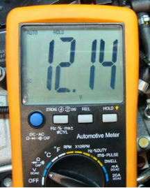
In order to check if the heater circuit is powered, plug the sensor connector to the Vehicle wiring loom and set the multimeter to Volts DC, with ignition on and engine off. By plugging the black lead of the multimeter to ground and the red lead to pin 5, normal battery voltage should be read.
| Ignition | On |
| Engine | Off |
| Connector | Plugged |
| Multimeter setting | Vdc |
| Multimeter Red lead | Pin 5 |
| Multimeter Black lead | Ground |
| Measured value | 12,14 Volt |
Checking the heater resistance:
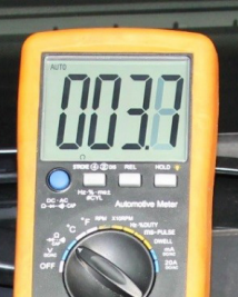
In order to check the heater resistance within the sensor itself, with key off and engine off, unplug the sensor connector and set the multimeter to 200 Ohms. To make the measurement, connect the black lead to pin 3 and the red lead to pin 5 of connector, sensor side. If the correct value is not known, it can be generally said that most wide band sensor heaters have a resistance of approx. 2,5 Ohms - 4 Ohms.
Checking the heater control circuit:
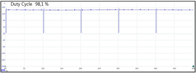
To view the electric control of the heater circuit, put the positive terminal of oscilloscope on pin 3 and put the oscilloscope reference to ground, with ignition on and engine idling.
| Ignition | On |
| Engine | Idle |
| Connector | plugged |
| Oscilloscope setting | Vdc |
| Positive terminal of oscilloscope | Pin 3 (Yellow wire) |
| Time/Div | 5 ms/Div |
| V/Div | 4 V/Div |
As shown, the heater circuit control shows a negative duty cycle characteristic, corresponding to roughly 2%, with 100 Hz frequency (the scope trace shows a different value, 98,1%, as the instrument default condition is set to calculate the positive value of the signal.
Monitoring the sensor signal:
As previously mentioned, wide band sensors can measure a range from very lean to very rich air/fuel ratios, this makes them ideal in diesel engines and lean concept direct injection petrol engines Testing these sensors involves a different approach. Wide band sensors have to be monitored by diagnostic tool. Measuring the pumping current by a multimeter is in most cases not possible in a standard workshop, as it requires particular instruments, capable of measuring very low values of current (standard multimeters cannot measure values of one or two milliamperes!). So a diagnostic tool is required. It is not common to monitor wide band sensors in diesel engines, as they always run with a wide mixture range. But such a test is very common and useful in direct injection petrol engines, where the lambda index can vary in a range between 0,8 and 2,5!
Observing pump current by a scan tool:
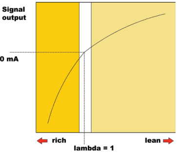
In “serial data” we can monitor the pump current as a positive or negative value. Also some scan tools will display an “Equivalency ratio equal to Lambda” as a graph. Through its polarity (minus or plus) we can understand if the engine is working with rich or lean mixture. In this example, just refer to the characteristic shown in the “Equivalency ratio equal to Lambda” graph, where lambda index v’s pumping current is shown.
MINUS SIGN of pumping current = rich mixture.
PLUS SIGN of pumping current = lean mixture.
In practice, upon acceleration enrichment (when depressing the accelerator), lambda (and pump current) quickly moves towards the negative area of graph (rich mixture), upon engine overrun (releasing the accelerator), lambda (and pump current) quickly move towards the positive area of graph (lean mixture).
Root causes of wrong lambda signals:
A bad or abnormal signal from a wide band sensor could originate from many different causes, and not necessarily by a defective lambda sensor. The signal could be interpreted as being abnormal due to the sensor ‘compensating’ for defects elsewhere.
Here are some causes:
- Incorrect mass air flow measurement, causing poor injector timing;
- Problems with fuel pump, injectors etc…
- Air leaks (in exhaust system/air intake circuit);
- Ignition system problems;
- Poor engine condition;
- Defective EGR valve.