Map Sensor
The function of the sensor
Intake manifold pressure sensors, also known as MAP sensors (from the English "Manifold Absolute Pressure"), are used together with the values of the throttle potentiometer to calculate the intake air mass of uncharged gasoline engines. (Figure 1). In the lower load range, the intake manifold pressure is strongly included in the calculation; at high engine loads, the throttle angle determines the air mass value. In turbo engines (diesel and petrol) the sensor is mainly used to control the turbocharging system. This is why it is often referred to as a boost pressure sensor. In turbocharged gasoline engines, both a boost pressure sensor upstream of the throttle valve and an intake manifold pressure sensor downstream of the throttle valve are often used.
The construction of the pressure sensor
The construction of the sensors is basically the same. Only the measuring range of the sensors is adapted to their intended use. There is a diaphragm in the sensor which curves according to the applied pressure. Strain gauges are attached to the diaphragm, which are stretched or compressed according to the curvature. The electrical resistance of the strain gauges changes with elongation. The change in resistance is processed by the sensor electronics and sent to the control unit as a signal. A pressure sensor has 3 electrical connections (Fig. 1). One pin has the supply voltage of 5 volts, the second pin has the signal voltage, which is normally between 0.2 V and 4.8 V. The signal ground is located on the third pin.If a fourth connection pin is present, the temperature of the intake air is additionally measured via an NTC resistor.
Such sensors are sometimes also referred to as "T-Map" sensors. The pin assignment of the sensors is unfortunately not standardized. You must take the assignment from the vehicle manufacturer's documentation or determine it from your own measurements, which are described in the following chapter.
Possible errors and their effects
Electrical failure of the intake manifold pressure sensor
The customer complains about jerking in the partial load range with gasoline engines without turbocharging, and loss of power with turbo engines. Possible causes are a lack of voltage supply, cable breaks, defective connectors or a failure of the sensor electronics. The control unit detects the fault and stores it in the fault memory.Common error messages are:"Suction pipe pressure or boost pressure signal implausible", "too low" or "too high". The control unit tries to produce emergency running characteristics with replacement values.The calculated values are displayed in the data list of the diagnostic device. Before replacing the sensor, please check the voltage supply (setpoint 5 V) and the lines to the control unit for continuity and ground fault. A circuit diagram is helpful for electrical measurements on the intake manifold pressure sensor.
Determining the connections without circuit diagram
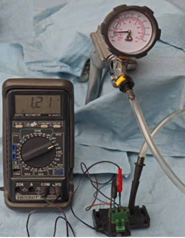
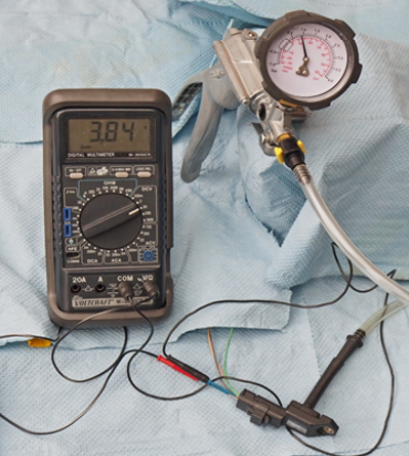
If the pin assignment of the sensor is not known, please proceed as follows: Connect a voltmeter to the battery ground and one of the three sensor pins (with the plug connected) and switch on the ignition. Measure the voltage at all pins of the sensor one after the other. A value of 5 volts is the voltage supply of the sensor. If the voltage is below 0.1 volts, it is the signal ground.Measure a value between 0.2 and 4.8 V at the pin of the signal voltage (Figure 2 and 3). For a map sensor with additional intake air temperature measurement, you can distinguish the pins for the temperature from the pin for the pressure by changing the pressure and/or temperature.
Typical signal values
In most cases, the pressure sensors emit an analogue voltage signal. Newer sensors emit a socalled frequencymodulated signal. The frequency of the signal increases with the pressure. To test this signal you need a frequency meter or better an oscilloscope. Exact typespecific set points can be found in the vehicle manufacturer's documentation. For the set points, check whether the pressure values are specified as absolute pressure or relative pressure. The absolute pressure scale starts with the absolute vacuum and the value of 0 bar. At atmospheric pressure the value is 1.0 bar. The relative pressure at atmospheric pressure is 0 bar. Values below atmospheric pressure have a negative sign.The absolute vacuum is -1.0 bar. Values above atmospheric pressure have a positive sign. Most manufacturers indicate the pressure as absolute pressure in Pascal (Pa), Hektopascal (hPa) or Kilopascal (kPa). 1hPa corresponds to one millibar (mbar). If you move the decimal point to the left by 2 digits for the kPa values, you get the value in bar. 120.0 kPa correspond to 1.2 bar. Standard pressure gauges display the pressure as relative pressure in bar. (See figure 4)
Incorrect measured values of the intake manifold pressure sensor
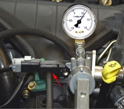
Incorrect measured values of the intake manifold pressure sensor do not necessarily lead to the storage of an error code in the error memory. If the measurement error is still within the tolerance range of the self-diagnosis, it is also possible that the self-diagnosis complains about another component, e.g. the throttle potentiometer or an overly lean mixture. If you suspect that the boost pressure sensor provides inaccurate measured values, you can check it most quickly using the data list of the diagnostic unit and a pressure hand pump (Fig. 4). Display the suction pipe pressure in the data list and connect a hand pump to the pressure sensor (Fig. 4). The display in the data list should correspond over the entire measuring range of the sensor to the pressure or vacuum that you have set on the hand pump.
Note: Some control units monitor the plausibility of the measured values with the engine stopped and the ignition switched on. If the measured values deviate too much from the atmospheric pressure with the engine stopped (this is the case when testing with the pressure pump), an error is set and the display is frozen to an emergency run value. In this case, you must check the pressure values with a voltage measurement.
Intake manifold pressure error with intact pressure sensors
For sparkignition engines without supercharging, the vacuum at idle should be between 400 and 500 mbar absolute (or between -600 mbar and -500 mbar relative). When the accelerator pedal is fully depressed, the pressure should be 900 to 1000 mbar absolute or -100 mbar relative to atmospheric pressure. The above values are guide values. Before making important repair decisions, please consult the vehicle manufacturer's target values. In the case of a leaky intake manifold, the pressure values are higher, particularly in idling and in the partial load range. Depending on the position of the leak, the mixture becomes too lean or too rich. In this case, check the entire intake manifold for leaks by spraying the intake manifold with suitable liquid (observe the safety rules!). If the test liquid hits the leak, the motor reacts with unstable running. Common causes are the intake manifold gasket, vacuum lines and the brake booster. Many manufacturers have provided pneumatic damping for pressure sensors that are connected to the intake manifold with a hose (see Fig. 1). This damping consists of a throttle (which can also consist of a calibrated bore in the connection pipe) and the volume of the connecting hose. If the damping is changed, the control unit calculates incorrect mean values for the suction pipe pressure. Check the function of the throttle and use a hose of the same length and inner diameter when replacing the connecting hose. In turbo engines, too low boost pressure leads to a loss of power. If the boost pressure sensor is OK, follow the path of the intake air through the engine and check the air filter, the turbocharger, the charge air lines with the charge air cooler and the exhaust gas recirculation and the particle filter, if present.