Diagnosis of inductive crankshaft and camshaft sensors
Task:
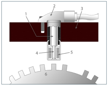
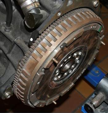
An Inductive sensor is a sensor without power supply. It is used in various applications including on gasoline and diesel engines to measure the engine speed and the position of the crankshaft or camshaft. The sensor consists of a permanent magnet surrounded by a coil (Fig. 1). The movement of an ‘encoder wheel’ attached to the shaft distorts the magnetic field and generates an alternating voltage. (Pictures 4 to 5). The encoder wheel, in relation to crankshaft sensors, often have many ‘teeth’ of which two are spaced wider apart (picture 2 and 3). This is the ‘trigger point’ and tells the control unit the exact position of the crankshaft. Each trigger corresponds to one revolution of the shaft. Without a crankshaft sensor signal, most passenger car engines would not be able to start.
Function:
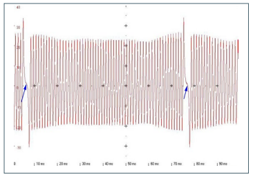
The control unit only evaluates the negative part of the AC voltage. The trigger point is -0.3 V on a falling edge, i.e. when the signal voltage changes from the positive to the negative range (Figs. 4 and 5). From the time interval between the trigger points, the control unit can recognise the engine speed and the crankshaft position. The signal evaluation of the camshaft sensor enables the control unit to determine whether the respective cylinder is on the compression or exhaust stroke.
Possible errors:
Most engines do not start after the failure of the crankshaft or camshaft sensor. If the crankshaft sensor fails while driving, the engine usually stops. If the camshaft sensor fails, the engine continues to run, but many engines cannot be started again after switching off. On some (eg. Certain VAG Group engines) the control unit injects fuel at TDC of the 1st cylinder on a trial basis and waits for the reaction of the engine. When the engine starts, it uses the crankshaft sensor to determine the position of the other cylinders. If the engine does not start, it tries again one revolution later. For many engines, if the crankshaft sensor fails, a fault may not be stored in the fault memory because the control unit assumes that the engine is stopped. If there is a suspicion of failure of the crankshaft sensor, display the engine speed and the camshaft speed in the data list via the tester/scan tool. During the starting process, the engine speed should be displayed as starter (cranking) speed of 200 to 300 RPM and the speed indicated by the camshaft sensor should be half the speed of the crankshaft. If a speed of 0 (zero) RPM is displayed during the start process, perform the following measurements to isolate the fault:
• Disconnect the sensor from the vehicle loom and measure its coil resistance (guide value: 500- 1500 Ω*) and also check the coil for short circuit to ground. If the resistance does not correspond to the set values of the manufacturer, the sensor must be replaced.
• Note some vehicle manufacturers require a ‘teach-in’ process of a new sensor with the tester/ scan tool to be carried out or a learning cycle during vehicle use*
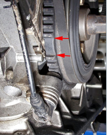
• Use a feeler gauge or depth gauge to check the distance between the sensor and the encoder wheel (guide value 0.8 mm -1.2 mm*). If the distance is too great, the signal voltage will be too low during the starting process and the engine may only fire at high starter speed. If the distance is too small, there is a risk that the encoder teeth will contact and damage the sensor. On some BMW engines (M41 and M51), the distance between the sensor and the transmitter wheel can be adjusted.
• Use a voltmeter in the AC range at the corresponding pins of the control unit to measure the signal voltage of the sensor. During the starting process, the meter should indicate one volt. If the signal voltage is too low, either the distance to the encoder wheel is too large or the permanent magnet in the sensor is weak.
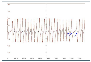
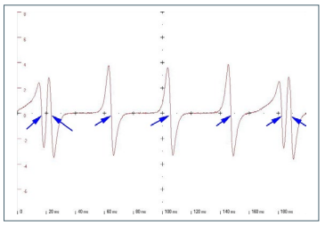
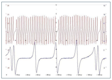
A measurement with an oscilloscope is a more meaningful diagnostic method. Then you will not only be able to judge the level of the voltage, but you will also be able to detect damage to the encoder wheel or reverse polarity of the cables from the signal shape. Encoder wheels can be damaged when being installed or when the toothed belt is changed. If you do not measure any voltage at the control unit, check the cables to the control unit for continuity, short-circuit between each other or an earth fault. If it is necessary to repair the cables from the sensor to the control unit, you must ensure that the two cables are not interchanged otherwise the engine will not start. The sensor still delivers a signal if the lines are reversed, but the signal is turned ‘upside down’ by the interchanged cables (Fig. 6). The control unit no longer recognises the position of the crankshaft correctly due to the shifted signals and can record a fault of ‘Synchronisation crankshaft/camshaft’. The same fault can be recorded if timing chains stretch due to high mileage or neglected maintenance (extended oil change intervals or incorrect engine oil grade) or material quality problems. The synchronisation of the crankshaft to the camshaft is no longer accurate due to the worn timing chain (often a rattle is heard). You can confirm the problem with a two-channel oscilloscope to pick up the signal from the crankshaft sensor and the camshaft sensor (Fig. 7). When idling, the signals of the two sensors may not be steady and constantly shift against each other.
*Before making repair decisions, please familiarise yourself with the target values and requirements of the specific vehicle model.