Diagnosis of hall sensors for crankshaft and camshaft
In recent years, Hall sensors have mostly replaced inductive sensors when fitted to passenger car engines because they deliver a square-wave signal even at low engine speeds, which no longer need to be processed in the control unit. In times of startstop systems, a faster engine start can be achieved.
Structure
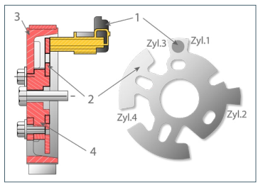
A Hall sensor is a sensor with a power supply. When used in petrol and diesel engines they measure the engine speed and the crankshaft or camshaft position. The sensor consists of a Hall element with an integrated permanent magnet triggered by a steel encoder wheel (Fig. 1) or a Hall element triggered by permanent magnetic encoder wheel (Fig. 2).
Function
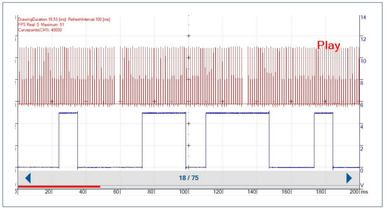
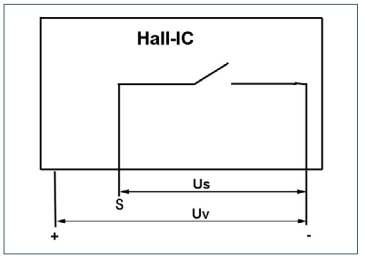
As the teeth of the encoder wheel passes the sensor, the magnetic field is distorted. The tension of the Hall element changes. The sensor then switches the signal voltage to ground, which is sent from the control unit to the sensor (Fig. 3). A square wave pulse voltage is generated when the encoder teeth pass, which can be measured against the signal ground (Fig. 4–6). A Hall sensor therefore has three connections. Power is supplied via 2 pins with 5 to 12 volts DC voltage. The third signal pin ‘S’ is supplied by the control unit with 5 to 12 volts which is sent to ground (earth).
Possible errors:
Most engines do not start after the failure of the crankshaft or camshaft sensor. If the crankshaft sensor fails while driving, the engine usually stops. If the camshaft sensor fails, the engine continues to run, but many engines cannot be started again after switching off. On some (eg VAG Group engines) the control unit injects fuel at TDC of the 1st cylinder on a trial basis and waits for the reaction of the engine. When the engine starts, it uses the crankshaft sensor to determine the position of the other cylinders. If the engine does not start, it tries again one revolution later. For many engines, if the crankshaft sensor fails, a fault may not be stored in the fault memory because the control unit assumes that the engine is stopped. If there is a suspicion of failure of the crankshaft sensor, display the engine speed and the camshaft speed in the data list via the tester/scan tool. During the starting process, the engine speed should be displayed as starter (cranking) speed of 200 to 300 RPM and the speed indicated by the camshaft sensor should be half the speed of the crankshaft. If a speed of 0 RPM is displayed during the start process, you can be sure that the corresponding sensor has been damaged. Perform the following measurements to isolate the fault:
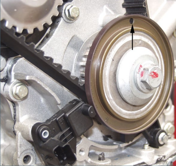
• Use a feeler gauge or depth gauge to check the distance between the sensor and the sensor wheel (guide value 1.0 mm -1.2 mm*). If the distance is too small, there is a risk that the teeth will damage the sensor. With some Peugeot engines (e.g. DW10), the distance between the sensor and the encoder wheel can be adjusted.
• Check with a voltmeter in the DC range at the pins of the sensor (Figure 2: + and -) the voltage supply (guide value for ignition on: 5 to 12V*). If there is no power supply, check the cables from the sensor to the control unit for continuity, short-circuit to ground and short-circuit to each other. If there is no supply voltage at the corresponding pins of the control unit despite intact cables, it is suspected that the control unit must be checked/replaced or repaired.
• Disconnect the sensor from the vehicle loom, then connect the voltmeter to signal pin ‘S’ and signal ground of the vehicle connector. A voltage of 5 to 12 V* should be applied. If the measurement result is 0 V (zero), check the signal line from the sensor to the control unit for continuity, short-circuit to ground and short-circuit to each other. If the signal line is OK and no voltage can be measured at the plug of the control unit, the control unit must be checked/replaced or repaired.
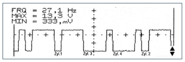
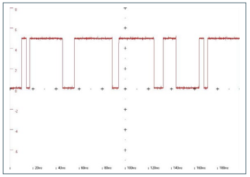
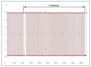
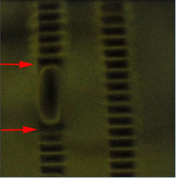
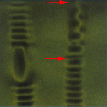
When the plug is connected, the signal voltage changes depending on the encoder wheel position. In this example, it could be 0, 5 or 12 V. If you then rotate the crankshaft, the voltage displayed by the voltmeter will change. When testing a camshaft sensor with only one pin for cylinder 1, this will require 2 crankshaft revolutions. If the signal voltage does not change, the Hall sensor is defective. Note some vehicle manufacturers require a ‘teach-in’ process to be carried out for a new sensor - with the tester/ scan tool, or a learning cycle during vehicle use*. Measurement of the signal voltage with an oscilloscope is a more meaningful diagnostic method as you can not only judge the level of the voltage, but also recognise damage to the encoder wheel from the shape to the signal (Fig. 4–6). Encoder wheels can be damaged when the gear unit is installed or when the toothed belt is changed. The encoder wheels with permanent magnetisation are particularly sensitive (Fig. 2). If these encoder wheels come into contact with a permanent magnet, e.g. when ‘fishing’ for a dropped screw with a magnetic tool or a hand lamp with a permanent magnet, the alternating magnetisation of the encoder wheel can be permanently damaged.
*Before making repair decisions, please familiarise yourself with the target values and requirements of the specific vehicle model.
As a result of the above, the control unit may record a fault of ‘synchronisation crankshaft/camshaft’ as a result of the magnetism damage (see Figs. 7 and 8). The same fault can be recorded if timing chains stretch due to high mileage or neglected maintenance (extended oil change intervals or incorrect engine oil grade) or material quality problems. The synchronisation of the crankshaft to the camshaft is no longer accurate due to the worn timing chain (often a rattle is heard). You can confirm the problem with a two-channel oscilloscope to pick up the signal from the crankshaft sensor and the camshaft sensor (Fig. 9). When idling, the signals of the two sensors may not be steady and constantly shift against each other.