Realtion of clogged DPF / EGR Valve and defective Glow Plugs. Glow Plug preventive maintenance
1. Premise
The September 2009 emissions standard EURO 5 covers diesel cars sold from January 2011 on, and the glow system begins to play an even more relevant role, crossing its strategies with several different engine systems. In the past, glow plugs were intended to only provide support when cranking a cold engine, nowadays they perform many tasks. On modern engines, without the driver being aware, glow plugs may even be being activated when a running engine is already hot. The glow system assists several other systems of diesel engines. In many situations it helps the engine not only to start but to run.
More in depth:
• It supports engine starting when cranking from cold.
• It allows a cold engine to run smoothly and silently as soon as started, with reduced smoke emissions.
• It gives a significant contribution when the DPF/ FAP (Diesel Particulate Filter/Filtre à Particules) needs to be regenerated.
• It helps to “protect” the EGR (Exhaust Gas Recirculation) valve from clogging/becoming stuck, as it can easily be affected by carbon: In particular, when exhaust/EGR gases are cold, the carbon can condense and create greasy, sticky deposits on the EGR components. Activating the glow plugs to increase the gas temperature helps to prevent the accumulation of these deposits and prevent the EGR from becoming clogged.
Recirculation and regeneration strategies:
EGR:
The relation between the EGR system and the glow system and the vital role of the glow system: The EGR system operation can easily become contaminated with carbon (This is the main reason for “defective” EGR Valves): As mentioned, when exhaust/EGR gases are too cold, the carbon can condense and create greasy, sticky deposits on the EGR components. This will in the end clog the EGR component, so that it becomes dysfunctional. Activating the glow plugs to increase the gas temperature helps to reduce the accumulation of these deposits and prevent the EGR from becoming clogged. This is very important for cars that are mainly driven in slow/short distance/city conditions, as the exhaust gas temperature is low in these driving conditions.
DPF / FAP:
The glow system and its role for the DPF / FAP: Glow plugs are very important for the regeneration of DPF/FAP to be completed successfully.
The glow system affects two aspects of the regeneration:
Firstly, powering the glow plugs allows the gases’ temperature to rise, so the DPF/FAP warms up to 600/650°C, which is required for a successful regeneration. It must be said that this is not the only way to create a temperature rise. For instance, to help the regeneration process, the throttle body valve is partially closed to reduce air and create a mixture richer in fuel. Furthermore, the EGR strategies can become disabled. On some makes, e.g PSA, the electrical demand can be increased for a time, by automatically and “secretly” powering the rear window heater/demister and heated mirrors, so the alternator causes an additional load on the engine. Activation of the glow system and resultant extra load on the electrical system also assists this. Secondly, if the glow system is not 100% operational (any associated fault stored or any real fault on glow plugs, control module or wiring) the regeneration process will not be allowed to begin! This commence as it will be inhibited. On this basis it becomes quite understandable how important it is for the glow system to be fully operational on diesel engines produced from EURO 5 specification onwards.
How to investigate glow systems
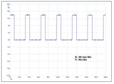
As already stated, the glow system must always be fully operational as it supports many other engine systems. Let’s now take a closer look at the electrical details and checks. Modern glow plugs are powered by their own control module. This means that each glow plug is not powered with 12V, but with a pulsing feed, better referred to as PWM (Pulse Width Modulation). Next pictures show a typical feeding pulse. This example comes from a MERCEDES-BENZ C180 CDI (W204), engine code 651.913.
Which are the fundamental parameters of the glow plug system being monitored by the engine electronics?
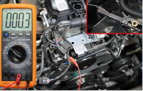
is to check for the resistance. This is done through the glow plug module. Why is the resistance so important? The resistance determines the amount of current flow through the individual glow plugs. Every time the ignition is switched on, the glow plug module performs a resistance check for each of the glow plugs. If any imbalance is detected, then the engine ECU is “informed” and a fault code is stored. Upon this, necessary recovery strategies will be activated (emergency/limp mode and/or MIL on), and eventually the DPF/FAP regeneration will be inhibited. On many cars the regeneration won’t start until correct glow system operation is restored. In order to make this explanation clearer, let’s measure the resistance of a glow plug from the same Mercedes-Benz engine mentioned above.
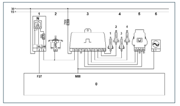
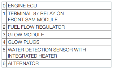
On the wiring diagram shown below, it can be seen that:
1) the glow module communicates with the engine ECU by pin 8 via LIN bus, also shared with the alternator;
2) it has a 12V 200A fused power feed and a smaller 20A fused one for electronics from the SAM (Signal Acquisition Module);
3) it powers the four glow plugs by pins 3, 4, 5 and 10;
4) although not crucial for the purposes of this article, the glow module is also connected with the water detection sensor with integrated heater, and with the fuel flow regulator.
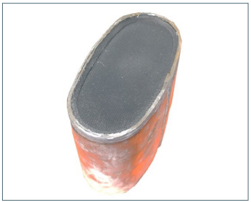
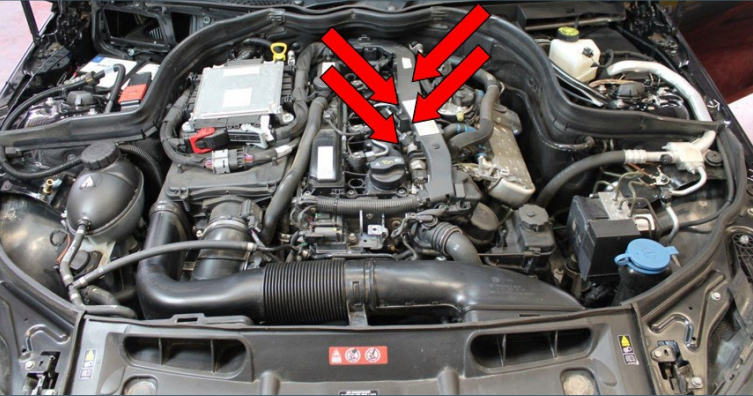
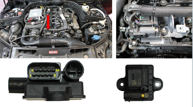
On this car the glow module is positioned towards the front of the engine. The picture shown also shows the pin reference, to support the schematics above. Once removed, the module appears as the images shown. Glow plugs may show different reference values; typically between 0,3 and 0,5 Ohms or sometimes more (it can vary depending on the glow plug’s characteristics, temperature, make and material). What has to be mandatory is that, when tested, all the glow plugs from the same engine show almost the same Ohm value. It is strongly recommended to test each resistance from the glow module connector, as it is then possible to check wiring continuity and resistance as well.
Summary:
If an engine has a problem with a clogged EGR valve or a clogged DPF, always check the correct function of the glow plugs. ! Modern common rail diesel engines will often start easily at temperatures above freezing, even with defective glow plugs. Very often this is why glow plug replacement is not performed immediately. However, as stated above, the glow plugs should not be ignored as they play an important role for other systems and therefore must always be fully operational.