Diagnosis of Direct Ignition Coils
Overview
Looking at trends and innovations in engine technology, it is easy to detect evolutionary growth, comprised of continuous upgrades and redevelopments in engine management strategies, the adoption of new components and improvements in the overall performance of modern engine units. All of this must be observed in light of the most important motivation; to reduce harmful and polluting emissions from combustion engines. It also shows how important it is to reduce fuel consumption, as this and the emission of CO2 are directly proportional to each other. One of the most popular ways to achieve these goals is that of direct injection systems. We will thus analyze the ignition systems adopted by a manufacturer using direct injection technology.
Our test case
VEHICLE: Ford Focus III
MOTOR: 1.0 Ecoboost (three cylinders, petrol, direct injection, turbocharged)
MOTOR CODE: M1DA
YEAR: 2013
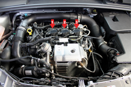
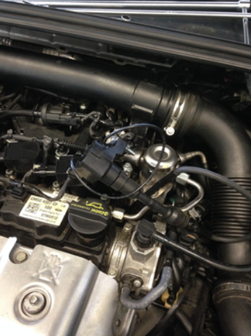
The EcoBoost engine is equipped with three single coils, one per cylinder, positioned as shown.
For their identification, the cylinder numbering begins on the timing belt side of the engine.
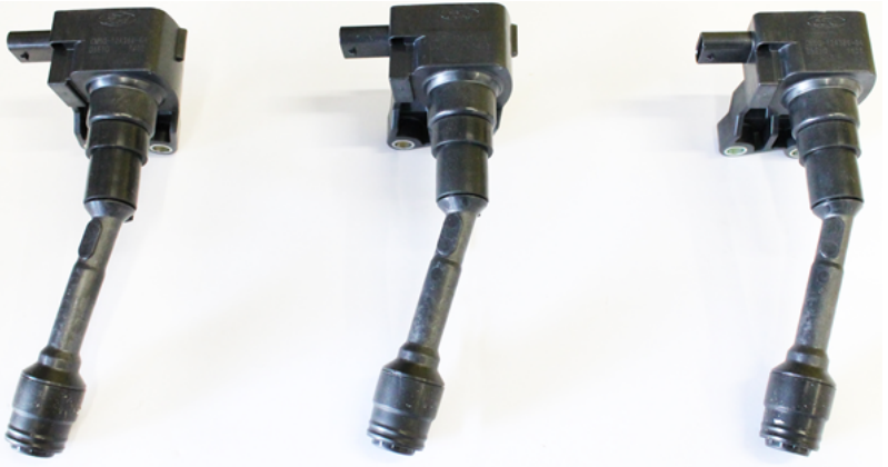
The coil replacement part is as follows: Reference NGK U5323
The shape of these coils looks unconventional, as they have an angled construction. It comes from the need to fit on the spark plugs, which are fitted at an angle; in order to work most effectively in accordance with the spray from the injector. In petrol direct injection engines the position and angle between spark and spray is very important for the quality of the combustion. Removal and refitting each coil is easy, only two screws and the connector need to be removed. In case of the described Ford engine no special tools or procedures are needed to remove the coils. Note: with other engines/ car manufacturers, special tools may be mandatory to properly remove the coils easily and without damaging.
Electrical check
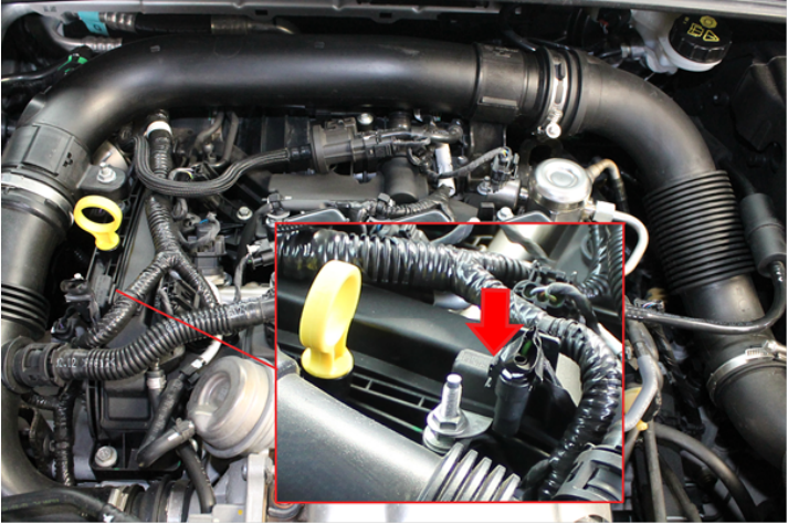
The engine control unit (ECU) sends an impulse command to each coil, after which the internal electronics of each coil provides the charge and the resulting spark. Lastly, the proper functioning of the ignition coils also uses a condenser, located near the oil level dip-stick, to filter electrical interference.
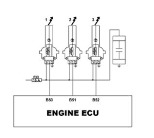
The primary side electrical connections to the individual coils are as follows:
pin 1 → Command from the engine control unit
pin 2 → Ground
pin 3 → Power supply via relay R14 and fuse F33 (engine bay)
The most important measurements to check the operation of the ignition coil are:
• Checking the supply voltage
• Checking ground terminal
• Checking the command impulse from the control unit
Measurements can be made through the use of a multimeter and oscilloscope.
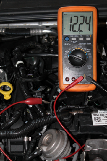
Checking the supply voltage
Analysis of the power supply via a multimeter on pin 3, which determines a value equal or greater than that of the figure below. (Battery voltage)
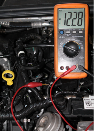
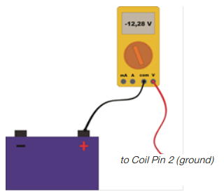
Checking Ground terminal
The combined ground terminal has been measured with reference to the positive. (see diagram). Also in this case, (negative) battery voltage should be displayed.
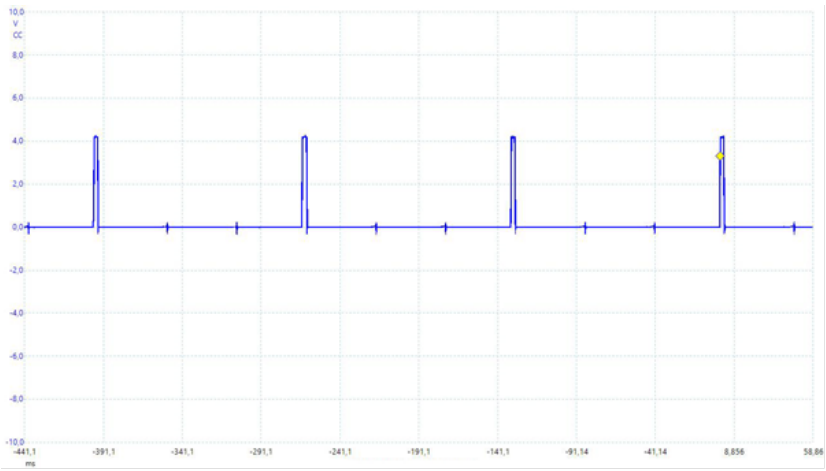
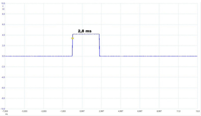
Checking the command impulse from the control unit
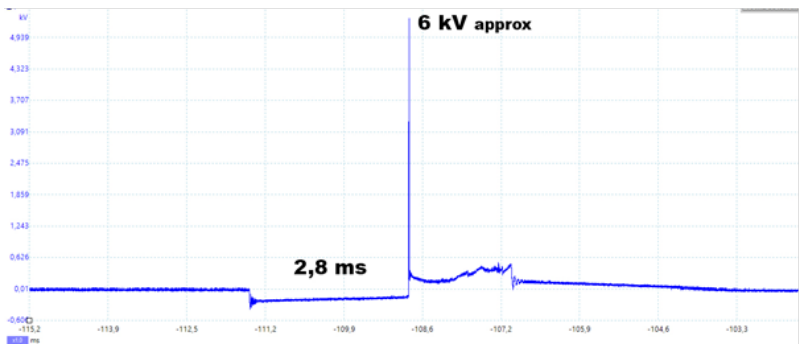
Now let’s look at the command given by the engine control unit to each coil. As noted, the coil does not receive the classic "ground-based" command, but rather the coil receives a square pulse signal. By this input, the internal electronics generates the jump in voltage on the primary coil, and then creates the secondary voltage via electromagnetic induction. The following image shows one of the pulses, zoomed in so as to measure its duration. Observing the command input shown, it is not possible to return the voltage to the peak reached in the primary, since - as mentioned - the sampled waveform is only an impulse. However, it is possible to observe up-close the duration of the pulse. Here, in our example it is 2,8 ms at idle. Note that in most engines, the coils actuation time is not constant, but mapped by the ECU depending on multiple conditions (for example engine load and speed, boost pressure). The presence of the command input signal only proves that the engine control unit is transmitting the pulse to each coil; but the actual transformation of the voltage between the coils internal electronics, primary and secondary coil windings, and the subsequent spark, is not assured. To ensure that the voltage on the secondary is actually present (meaning the coil is working), the high voltage has also been determined, using specific test equipment for kV measurements.
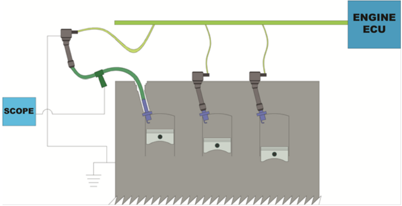
To do this measurement, the coil was removed from the spark plug shaft (primary connector stays connected), then an adaptor wire from coil to spark plug was installed. The inductive pickup of the test equipment was connected to this wire. Note that the ground connection of this coil is established by the coil mounting screws, so a separate ground connection needs to be created.
Diagnostics
Finally, here is a list the most common fault codes relative to the electrical failure of each coil.
P0351 = PRIMARY/SECONDARY IGNITION COIL CIRCUIT A
P0352 = PRIMARY/SECONDARY IGNITION COIL CIRCUIT B
P0353 = PRIMARY/SECONDARY IGNITION COIL CIRCUIT C
Such codes refer to an electrical issue, like a broken winding or short circuit. Please also consider the misfiring fault codes, which could originate from a coil malfunction (and many other root causes!).
P0301 = CYLINDER 1 MISFIRE DETECTED
P0302 = CYLINDER 2 MISFIRE DETECTED
P0303 = CYLINDER 3 MISFIRE DETECTED
The easiest method in this case to discriminate a fault coming from the coil or other, is interchanging the “suspected” coil with one from another cylinder. If the misfiring cylinder “moves” with the coil, the coil is the root cause. If the misfiring stays with the same cylinder, the coil can be excluded from causing the problem.